Projection optical system and image display apparatus

a technology of projection optical system and image display apparatus, which is applied in the direction of optical elements, lenses, instruments, etc., can solve the problems of increased cost, difficult manufacturing of mangin mirrors, and inability to readily apply to reflective light valves such as lcos

Active Publication Date: 2007-11-01
RICOH KK
View PDF3 Cites 38 Cited by
  • Summary
  • Abstract
  • Description
  • Claims
  • Application Information

AI Technical Summary

Problems solved by technology

The projection optical system disclosed in Patent Document 1 has a short back focal distance and is not telecentric on the object side, so that it is not readily applied to a reflective light valve such as LCOS.
However, the Mangin mirror having negative power is used for the catoptric system and manufacturing of the Mangin mirror is difficult in comparison with manufacturing of a normal mirror and a cost thereof is increased.

Method used


Image

  • Projection optical system and image display apparatus
  • Projection optical system and image display apparatus
  • Projection optical system and image display apparatus

Examples


numerical example 1

[0087]Table 1 shows data on numerical example 1.

[0088]In Table 1, “No.” is a surface number from the object side including both sides of the transparent plate referenced at reference numeral 2 and a surface of the diaphragm 3. No. 0 indicates the object surface and No. 15 indicates the surface of the diaphragm 3. R indicates radius of curvature, D indicates a space between surfaces, Nd indicates a refractive index of a material relative to d line, and vd indicates an Abbe number.

TABLE 1No.RDNdνdNote00.0027.25Objectsurface10.0036.901.51764.120.004.85345.1122.411.49781.64−126.860.105183.631.601.78644.2631.3110.991.49781.67−145.020.10871.1310.391.49781.69−33.791.601.83437.11050.680.101147.3129.421.62036.312−36.810.2413−35.3640.691.48870.414−71.370.10150.0092.73Diaphragm16104.7775.051.77349.617−195.6814.0418−71.181.601.60360.51966.4415.0020−31.0726.221.69636.221−497.888.12220.0049.501.49257.8Asphericalsurface230.00192.49Asphericalsurface24−133.33−250.00Asphericalsurface250.00300.00Refle...

numerical example 2

[0119]Table 5 shows data on numerical example 2.

[0120]In Table 5, “No.” is the surface number from the object side including both sides of the transparent plate referenced at reference numeral 2 and the surface of the diaphragm 3. No. 0 indicates the object surface and No. 15 indicates the surface of the diaphragm 3. R indicates radius of curvature, D indicates the space between surfaces, Nd indicates the refractive index of the material relative to d line, and vd indicates an Abbe number.

TABLE 5No.RDNdνdNote00.0027.25Objectsurface10.0036.901.51764.120.004.85354.5810.391.49781.64−147.7013.485203.761.601.78644.2635.189.551.49781.67−145.330.10897.129.451.49781.69−35.549.181.83437.110−420.4921.9611−1041.309.831.62036.312−63.984.0713−58.6910.001.48870.414−67.20114.08150.00112.59Diaphragm1696.148.321.77349.617−566.0132.5218−66.6810.001.60360.51969.0018.9520−32.647.061.69636.221−134.3527.11220.0013.751.49257.8Asphericalsurface230.0058.88Asphericalsurface24−133.33−274.16Asphericalsurface25...

numerical example 3

[0165]Tables 9, 10, and 11 show data on numerical example 3.

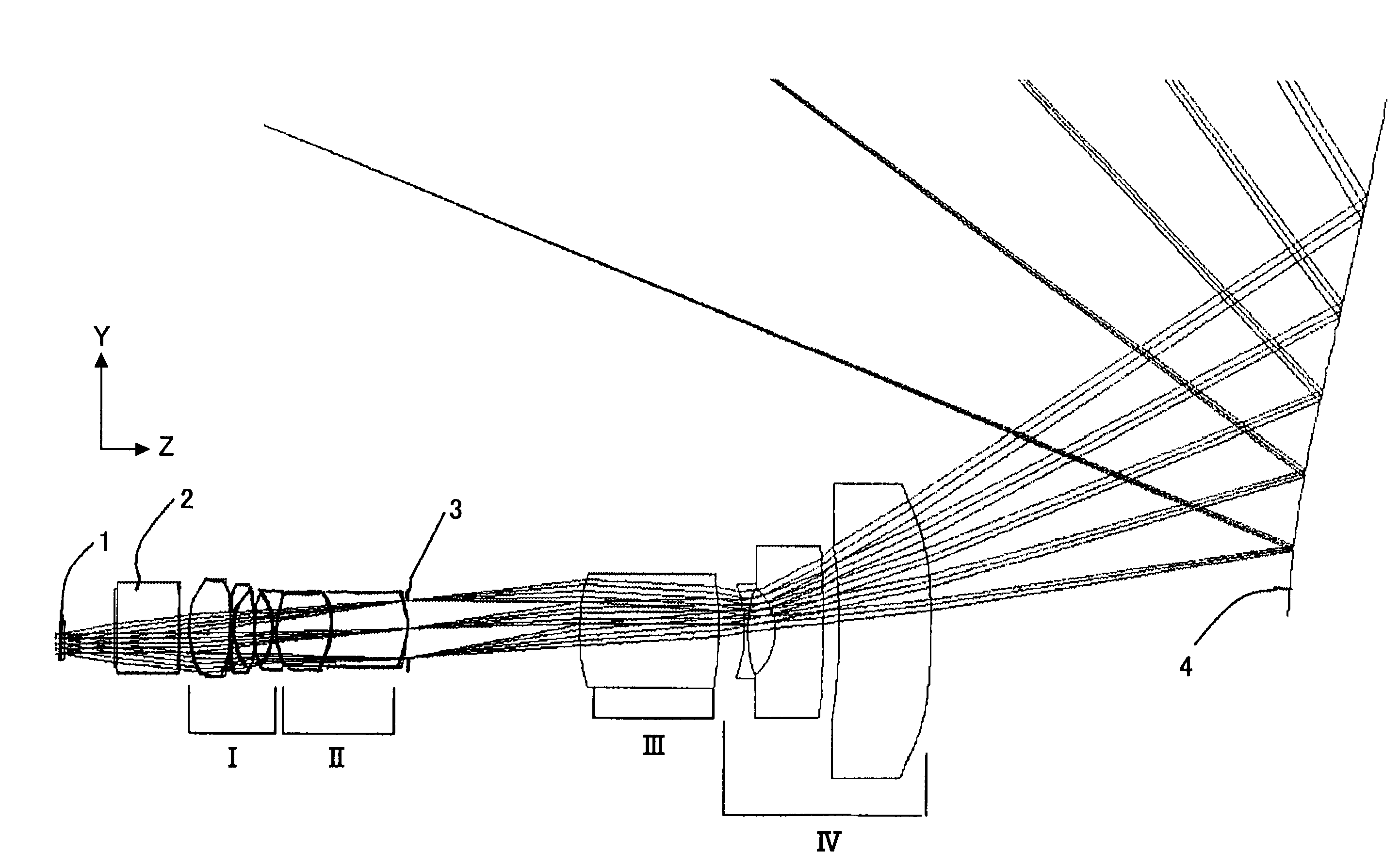
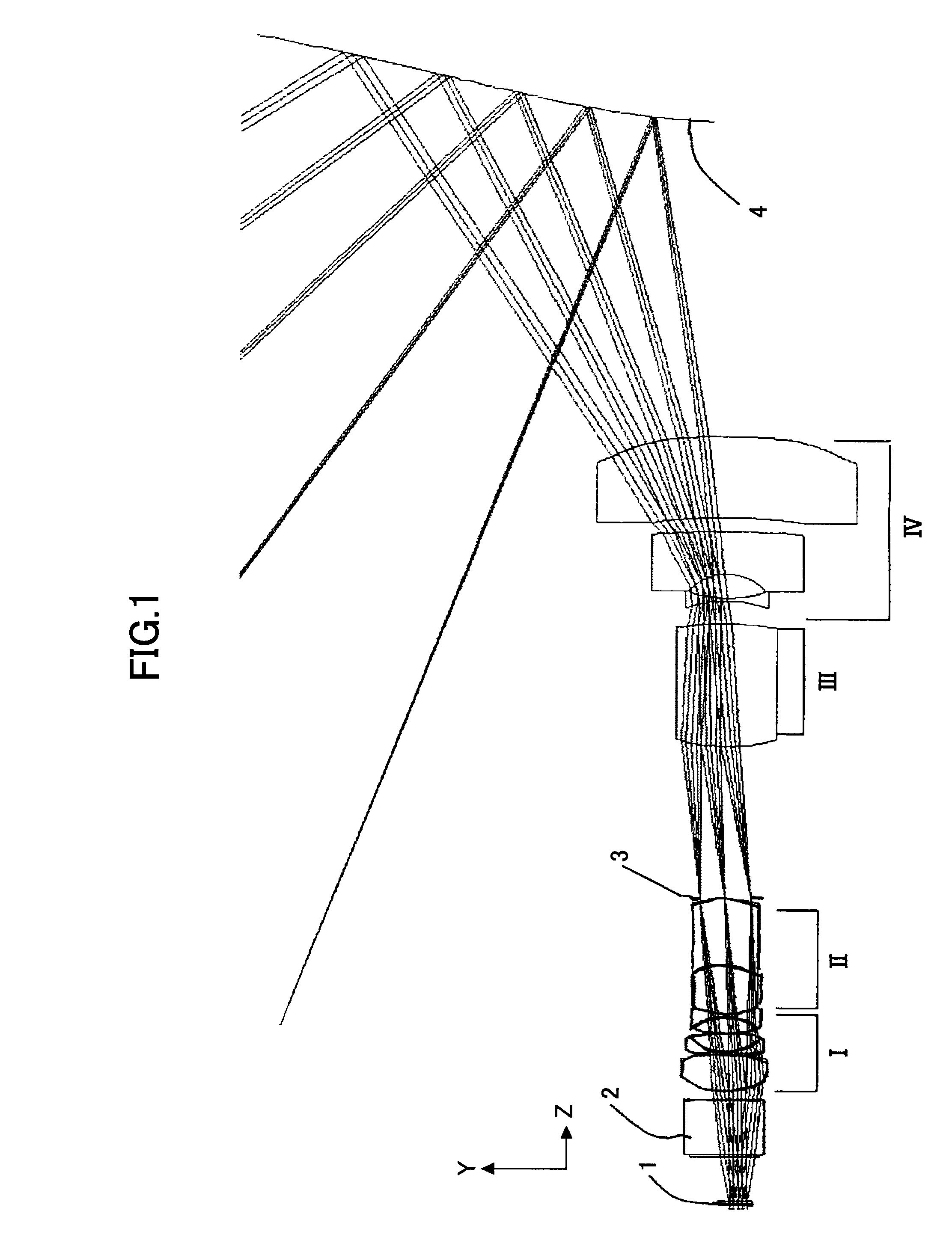
[0166]In Table 9, surface number is a number from the object surface including both sides of the transparent plate 2 in FIG. 9. Surface 1 (S0) indicates the object surface, surfaces 11 to 17 (S11 to S17) indicate the first lens group I, surface 19 (S19) indicates the diaphragm, surfaces 20 to 23 (S20 to S23) indicate the second lens group II, surfaces 24 to 25 (S24 to S25) indicate the third lens group III, surfaces 26 to 31 (S26 to S31) indicate the fourth lens group IV, surface 32 (S32) indicates an aspherical mirror, surface 33 (S33) indicates a plane mirror for returning, and surface 34 (S34) indicates the image surface. Surfaces 30, 31, and 32 indicate aspherical surfaces. “INF” indicates a plane. The above-mentioned description of Table 9 applies in the following tables (13, 17, 21, 25, 29, 33, 37, 41, 45, 49, 53, 57, 61, 65, 69, and 73) in the same manner.

TABLE 9CurvatureAbbeSurfaceradiusSpaceRefractivenumbernumber(m...


PUM


Abstract

A disclosed projection optical system for projecting and forming an enlarged image of an image displayed in a planar manner as an object includes: a lens system including, from an object side, at least a lens group providing telecentricity to an object space side, a lens group controlling divergence of angles of view, a diaphragm, a lens group converging the angles of view, and a lens group converging and subsequently enlarging the angles of view; and a catoptric system disposed on an image side relative to the lens system and including a mirror having negative power. Each lens group of the lens system and the mirror having negative power share an optical axis and the optical axis is shifted relative to a center of an object surface.

Description

BACKGROUND OF THE INVENTION[0001]1. Field of the Invention[0002]The present invention relates to a projection optical system and an image display apparatus.[0003]2. Description of the Related Art[0004]Image display apparatuses of projector type are known in which still images such as characters, pictures, and the like and moving images two-dimensionally displayed on a small-sized light valve are enlarged and projected for image display through a projection optical system. Examples of light valves include transmissive liquid crystal panels, DLP (Digital Light Processor), and LCOS (Liquid Crystal on Silicon) superior in contrast characteristics.[0005]Examples of image display apparatuses include front projection types in which an image on the light valve is enlarged and projected onto a projection surface such as a reflective screen disposed at a distance from the apparatus, and then a reflected light is viewed and rear projection types in which a transmissive screen is disposed insid...

Claims


Application Information

Patent Timeline
Patent Type & Authority Applications(United States)
IPC IPC(8): G02B9/34
CPCG02B13/16G02B17/08G02B17/0852H04N9/3197G03B21/28H04N9/3152G03B21/10
Inventor TAKAURA, ATSUSHIABE, ISSEIFUJITA, KAZUHIRO
Owner RICOH KK
Why Eureka
Try Eureka