

Capacitor Device
a technology of capacitors and terminals, applied in the direction of fixed capacitors, variable capacitors, electrochemical generators, etc., can solve the problems of not being able to reduce in size, not being able to reduce the mounting space in all, and not being able to make the connection of positive electrode terminals so easy, so as to reduce the space required for the connection, reduce the undesirable resistance, and facilitate the connection
- Summary
- Abstract
- Description
- Claims
- Application Information
AI Technical Summary
Benefits of technology
Problems solved by technology
Method used
Image

Examples
first exemplary embodiment
[0063] Description is provided concretely of one mode of the present invention by using the first exemplary embodiment below.
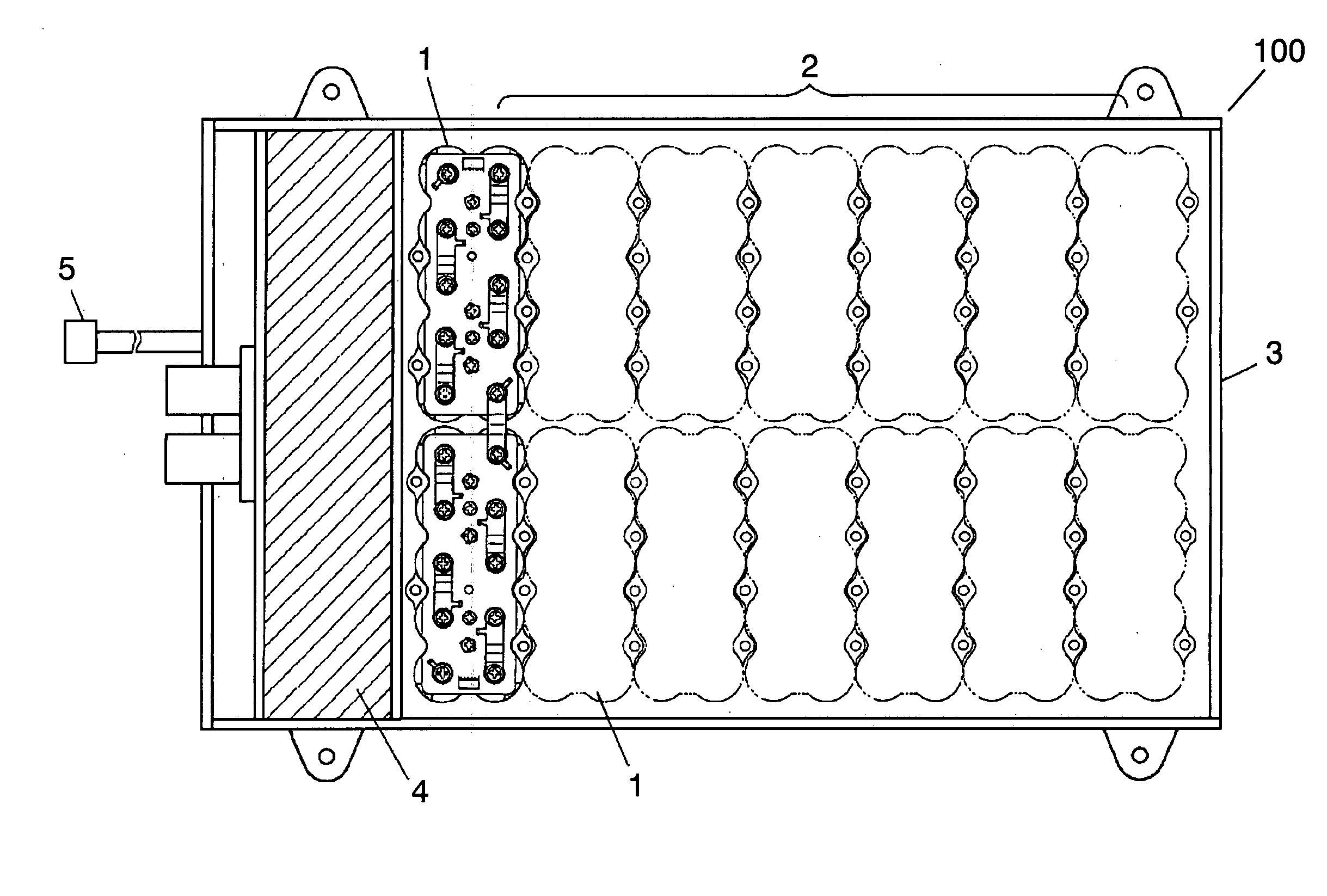
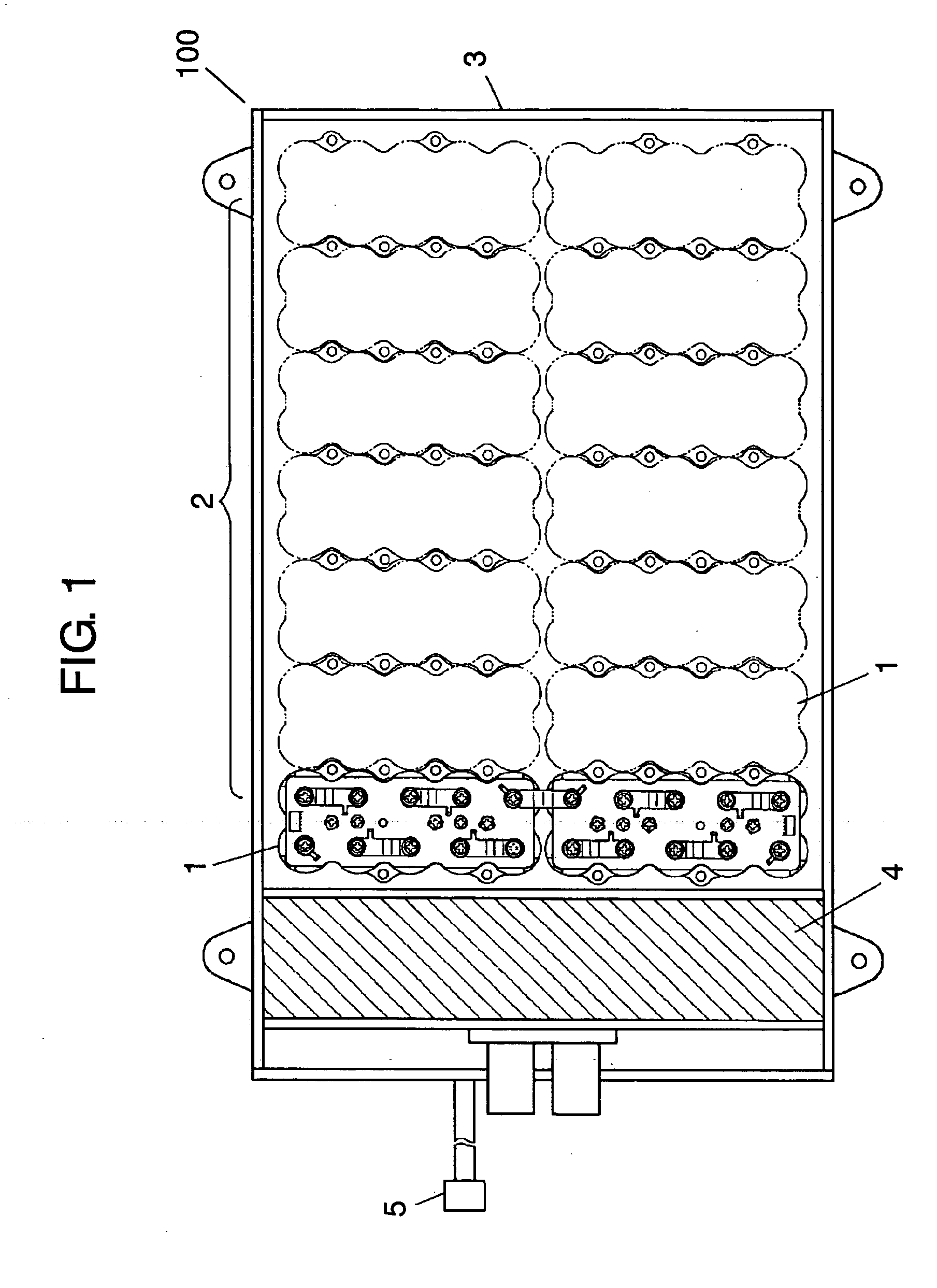
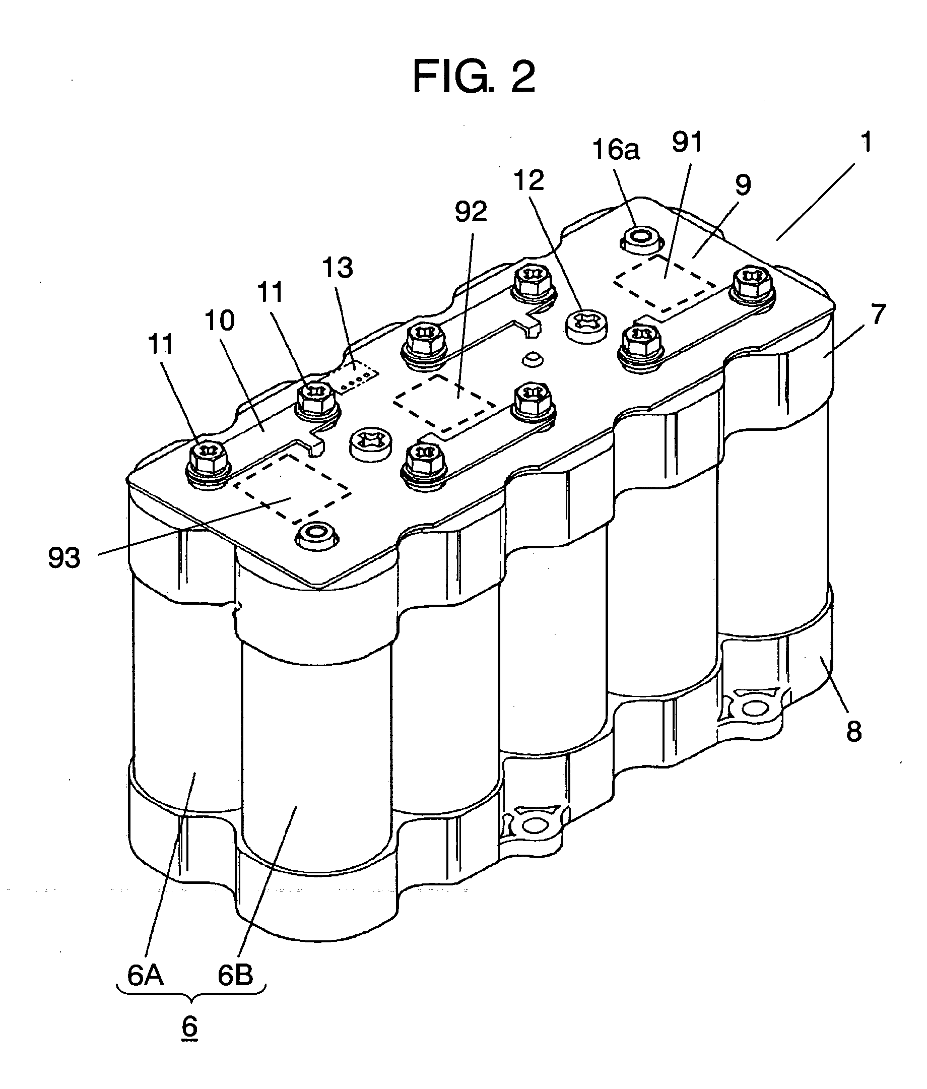
[0064]FIG. 1 is a plan view depicting a structure of a capacitor device according to the first exemplary embodiment of the present invention, and FIG. 2 is a perspective view depicting a structure of subunit 1 used in the capacitor device.
[0065] As shown in FIG. 1 and FIG. 2, capacitor device 100 comprises subunit 1 having a mutually connected plurality of capacitor units 6, each of which comprises two pieces of serially connected and coupled capacitors having opposite polar orientations to each other (i.e., a first capacitor and a second capacitor). A plurality of subunits 1 are connected to compose main unit 2. Main unit 2 is then stored inside case 3. Case 3 contains controller 4 for controlling main unit 2, and input-output connector 5.
[0066] Subunit 1 has five sets of coupled capacitor units 6, as shown in FIG. 2. Each of capacitor units 6 comprises fi...
second exemplary embodiment
[0081] Description is provided hereinafter of another mode of the present invention by using the second exemplary embodiment.
[0082] A capacitor device of the second exemplary embodiment has subunit 201, a structure of which differs partly from that of capacitor device 100 described in the first exemplary embodiment. Since the structure other than the above is analogous to that of the first exemplary embodiment, like reference marks are used to designate like components, and description will be provided of only the different portions, with reference to the accompanying drawings while details of the like components are skipped.
[0083]FIG. 4A to 4C are a plan view, a front view and a side view depicting the structure of subunit 201 of the capacitor device according to the second exemplary embodiment of the present invention. Subunit 201 comprises bus bars 20, each electrically connecting adjoining terminals 16a of capacitor units 6, and bent portion 20a provided in each bus bar 20 by ...
third exemplary embodiment
[0086] Description is provided hereinafter of still another mode of the present invention by using the third exemplary embodiment.
[0087] A capacitor device of the third exemplary embodiment has one of subunits 301 and 302, structures of which differ partly from that of capacitor device 100 described in the first exemplary embodiment. Since the structures other than the above are analogous to that of the first exemplary embodiment, like reference marks are used to designate like components, and description will be provided of only the different portions with reference to the accompanying drawings while details of the like components are skipped.
[0088]FIG. 5A is a sectional view depicting a main part of the structure of subunit 301 of the capacitor device according to the third exemplary embodiment of the present invention. Subunit 301 has first capacitor 6A, upper holder 7 and terminal 16a.
[0089] There is O-ring 22 made of rubber placed between a peripheral edge on an upper surfac...
PUM
 Abstract
Description
Claims
Application Information