
Insulation of a switchgear device of vacuum cartridge type by insert moulding

a switchgear device and vacuum cartridge technology, applied in the field of switchgear units, can solve the problems of reducing the rigidity of the insulator, affecting the operation of the substation, and the type of insert moulding is not optimized, and achieves the effect of sufficient rigidity

Inactive Publication Date: 2012-05-15
SCHNEIDER ELECTRIC IND SAS
View PDF21 Cites 20 Cited by
  • Summary
  • Abstract
  • Description
  • Claims
  • Application Information

AI Technical Summary

Benefits of technology

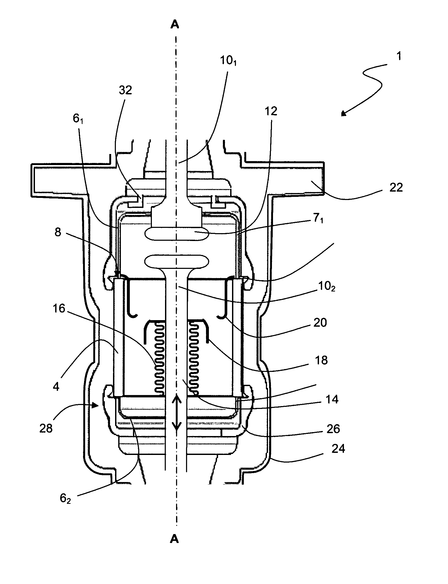
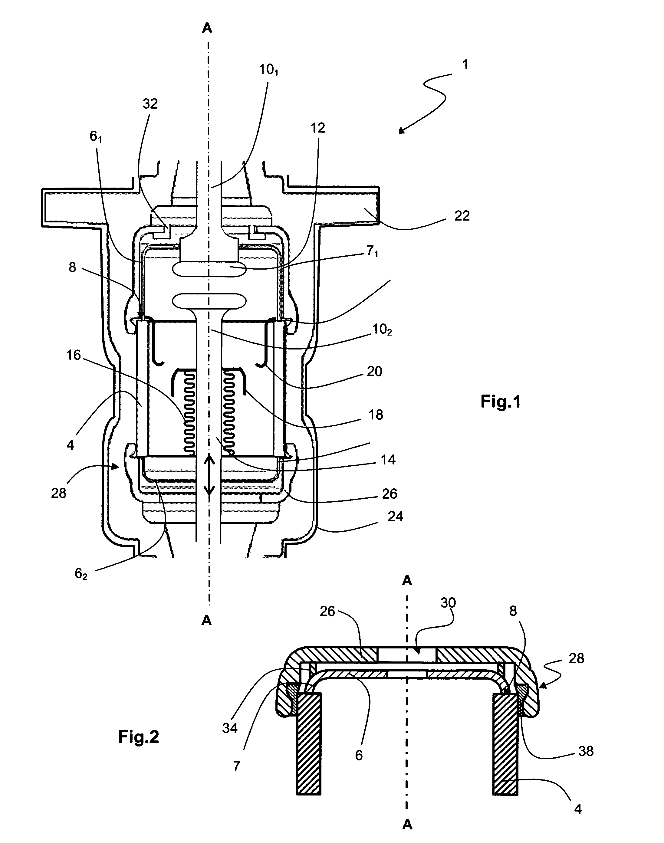
[0014]The switchgear device according to the invention further comprises two cover-plates covering each of the covers and protecting their junction area with the tubular part. In particular, the cover-plates are in the form of bowls with a bottom wall substantially perpendicular to the axis of the switchgear device, and a peripheral wall extending along this axis over a sufficient distance to cover the side wall of the cover and also an end part of the insulating tube. The thickness of the cover is determined by its role of mechanical strengthener, with elimination of the fragile points of square edge type. Means, for example a direct contact, are provided to prevent the creation of a potential difference between both. A conducting spacer can separate the bottom of the cover-plate from the bottom of the cover in the longitudinal direction for ease of connection of the switchgear device assembly means.
[0015]The cover-plates are sufficiently rigid to act as mechanical strengtheners, and they are advantageously designed to act as dielectric deflectors—in particular, they do not present any square edges on their external surface and they can present bulges at the level of the junction points between insulator and conductor. It is moreover preferred for a seal to be present between the insulating tubular part and cover-plate so as to protect the junction area between cover and tubular part by locating it in a clean space. The seal can be made from elastomer and is advantageously fitted in a suitable groove of the cover-plate. Thus, in addition to mechanical protection against a higher external pressure, the braze is protected against fluid infiltration.

Problems solved by technology

These solutions generate a notable volume occupation of the cartridge, the latter further being cumbersome to implement.
This type of insert moulding is however not optimized, in spite of a malleable or elastic layer being able to be possibly inserted between the coating and the cartridge, on account of the different coefficients of thermal expansion of the ceramic cylinder, of the metal bowls and of the epoxy coating, which can cause cracking, or even breaking, of the insulator.
Use of the latter as vacuum cartridge coating has however been limited due to their forming conditions.
Insert moulding by such a material, performed under high pressure, is liable to damage the coated components, in particular the fragile elements such as vacuum switches or fuses which comprise welds.

Method used


Image

  • Insulation of a switchgear device of vacuum cartridge type by insert moulding
  • Insulation of a switchgear device of vacuum cartridge type by insert moulding

Examples


Embodiment Construction

[0020]A vacuum cartridge 1 according to the invention, illustrated in FIG. 1, is designed for use in a switch to perform breaking in an electric circuit. The cartridge 1 according to the invention is preferably arranged to operate at high or medium voltage, i.e. between 1 and 75 kV or 52 kV, although use in low voltage is possible. Cartridge 1 comprises a sealed chamber, or envelope, 2 in which a controlled low pressure of air or another dielectric fluid preferably prevails, i.e. a vacuum. The chamber 2 is defined by a longitudinal enclosure extending along an axis AA, and that is advantageously axisymmetric (symmetric in revolution) for reasons of manufacturing and assembly.

[0021]The enclosure of chamber 2 comprises a first insulating central main part 4, advantageously made from ceramic although glass may be an option. The insulating part 4 is tubular, preferably cylindrical in revolution to optimize its mechanical and dielectric strength, and also to facilitate manufacture thereo...


PUM


Abstract

A vacuum cartridge (1) is manufactured with a dielectric coating (22) made from elastomer directly on the enclosure of the chamber (2) of the cartridge (1). To prevent the elastomer from infiltrating into the chamber (2) of the cartridge and / or its enclosure from breaking, cover-plates (26) performing mechanical protection and dielectric deflection cover the covers (61, 62) of the chamber (2) and their braze (8) with the ceramic tube (4).

Description

[0001]This application is a national stage entry of International Application No. PCT / FR2008 / 001788, filed Dec. 19, 2008 designating the U.S., which claims the benefit of French Application No. 07 / 08970, filed Dec. 21, 2007.BACKGROUND OF THE INVENTION[0002]The invention deals with switches and switchgear units, in particular vacuum cartridges, operating in particular in high and medium voltage. The invention relates to insulation of such equipment by coating with a suitable material.[0003]The invention relates to insulation of a switchgear device by injecting an elastomer in order to over-mould said switchgear device. To palliate a break in its enclosure, or possible infiltrations of the elastomer into the chamber of the switchgear device, the junction areas of the enclosure are protected by mechanical strengtheners that are also dielectric deflectors.STATE OF THE ART[0004]A vacuum cartridge is formed by an extinguishing chamber in which a low pressure prevails and in which there ar...

Claims


Application Information

Patent Timeline
Patent Type & Authority Patents(United States)
IPC IPC(8): H01H33/662
CPCH01H33/66207H01H85/047H01H2033/6623H01H2033/66284
Inventor MARTIN, LUDOVICMENNESSIER, CHRISTIANHERAULT, CATHERINECHATELET, BRUNO
Owner SCHNEIDER ELECTRIC IND SAS
Learn More