Piston coolant gallery

a coolant gallery and piston technology, applied in the direction of engine components, mechanical equipment, foundry moulding equipment, etc., can solve the fundamental limit of the compression ratio of a spark-ignition, gasoline engine, and the material used in the construction of such engines is under severe stress, so as to reduce the thickness of the section, the effect of introducing distortions of the stress field and facilitating stress analysis

Inactive Publication Date: 2007-10-16
SENECA TECH
View PDF5 Cites 33 Cited by
  • Summary
  • Abstract
  • Description
  • Claims
  • Application Information

AI Technical Summary

Benefits of technology

[0041]Multiple, individually localized, gallery extensions according to the invention—with their local reduction of section thickness—are much less problematic. Generally, in casting such localized gallery extensions, a salt core would have to be positioned with respect to the cast under-crown, the Ni-resist insert (if present), and an adequate distance from machined features such as bowl and ring grooves.
[0042]In the case of conventional pistons using substantial section piston (gudgeon) pins to connect the piston to the small end of the connecting rod, bending stresses arising from lack of support of the piston at its center (i.e. between bosses), and “wrap” of the piston around the piston pin, both introduce distortions of the stress field. Extensions running substantially along, or parallel to, the axis of the piston will act as stress raisers to any of the stresses that are not along the axis of the piston, because of the bending described above. These stresses are not the major stresses in the piston, but the stress-raising effect of the extensions will make the situation somewhat worse.
[0043]In the case of spherical-jointed pistons, where a substantive piston pin is replaced by a ball-and-socket joint, stress analysis is somewhat easier and the bending stresses described above do not arise, so cannot be amplified by the extensions.
[0044]Generally, any significant extension will increase the surface area exposed to the coolant. Conventional feed and drain holes, spokes etc., have addressed this rather arbitrarily in past designs. However, there has been no previous attempt to include a multiplicity of such features in a cast gallery (in a cast piston) for the express purpose of (coherently) improving cooling, by increasing the wetted surface area, as envisaged according to the present invention.

Problems solved by technology

The materials used in the construction of such engines are under severe stress and there is little margin between a robust, cost-effective design and one that will have insufficient durability.
A fundamental limit upon the compression ratio of a spark-ignition, gasoline engine, and hence its thermodynamic and fuel combustion efficiency, is the phenomenon of pre-ignition, or “knock”, that is, uncontrolled explosion, rather than progressive timed combustion.
The destructive effect of knock is well-known, and much effort has been expended in its resolution.
However, the high compression ratios employed by diesel engines for higher thermodynamic and fuel combustion efficiency have led to diesel engine pistons needing sophisticated piston cooling systems.
Until the advent of finite element stress analysis, the extremely complicated thermal and mechanical stresses in pistons could not be effectively calculated and so piston designers had limited formal (quantifiable) guidance.
Many complex and imaginative solutions were tried, but few were successful.
However, the problem of piston temperature remained.
Component cooling around the working fluid is a trenchant problem.
The coolant also degrades if the wetted surfaces become too hot.
High thermal gradients in components, arising from intensive heating and cooling, also produce high thermal stresses.
A piston is closest to the working fluid and the intense heat of combustion and is thus the component most vulnerable to thermal and mechanical stresses and shock.
Piston structures suffer localized extreme temperature gradients and working pressures.
Consequently, in piston engine development, piston temperature and hence piston cooling has long been an important issue.
Blind holes do not allow fluid to flow in the normal (e.g. coherent uni-directional, continuous, closed-loop, re-circulatory) sense.
However, because of the severe accelerations experienced by the piston in its reciprocating motion, coolant fluid is thrown into and out of the holes upon each piston reversal and hence has high, albeit intermittent, flow velocities, in relation to the sides of these blind holes, thus promoting heat transfer.
For smaller engines where initial cost (i.e. original manufacturing, as opposed to service-life) is more important and space is limited, hitherto known blind-hole coolant gallery configurations have proved impractical for the majority of applications.
Many minor modifications to galleries have been proposed hitherto, with specially shaped entrances and exits, tilted axes, convergent or divergent walls, etc. but none of these have achieved a significant increase in overall surface area for heat transfer through a coolant medium.
In one approach an oil jet projecting oil at the underside of the cast aluminum piston was the easiest and lease expensive solution, but one which only increased the allowable rating by some 25-30%.
These pistons had less effective cooling than many more complex designs, and so operated at higher temperatures, but their simplicity of construction entailed lower stress levels.
The narrow channels of a cooling coil could not be run only partially-filled, because the oil flow-rate required to carry away the heat flow could only be sustained in such narrow passages by filling them with oil.
Many, many different features have been tried on galleries to increase their efficiency, but without an analytical tool capable of predicting the flows at a detail level, there was little prospect of progress, except by accident.
The limited surface area available for heat transfer means that the bulk piston temperature is not reduced as much as is possible.
This feature was commonly adopted, but careful sizing of inlet and drain holes, to match them to the gallery size and the oil flow rate, has made this feature redundant.
Cast galleries have tended to be very simple, partly because of the limitations of the foundry processes, and also because of the dangers of introducing stress raisers.
Foundry processes are also such that changes in section are always accompanied by the danger of porosity, “cold-shuts”, and other similar defects that effect the integrity and strength of the metal locally.
Incorporation of a coolant gallery into the piston entails some additional cost, but its overall cost-effectiveness is witnessed by its widespread adoption in highly-rated diesel engines, where piston temperatures would otherwise pose a problem.

Method used


Image

  • Piston coolant gallery
  • Piston coolant gallery
  • Piston coolant gallery

Examples


Embodiment Construction

)

[0055]The terms “upper” and “lower” as used herein relate only to relative positions of components shown in the diagram. In a working engine, or pump, the components may be arranged in any appropriate orientation consistent with provision for lubrication, cooling, fuel feed and combustion intake and exhaust flows.

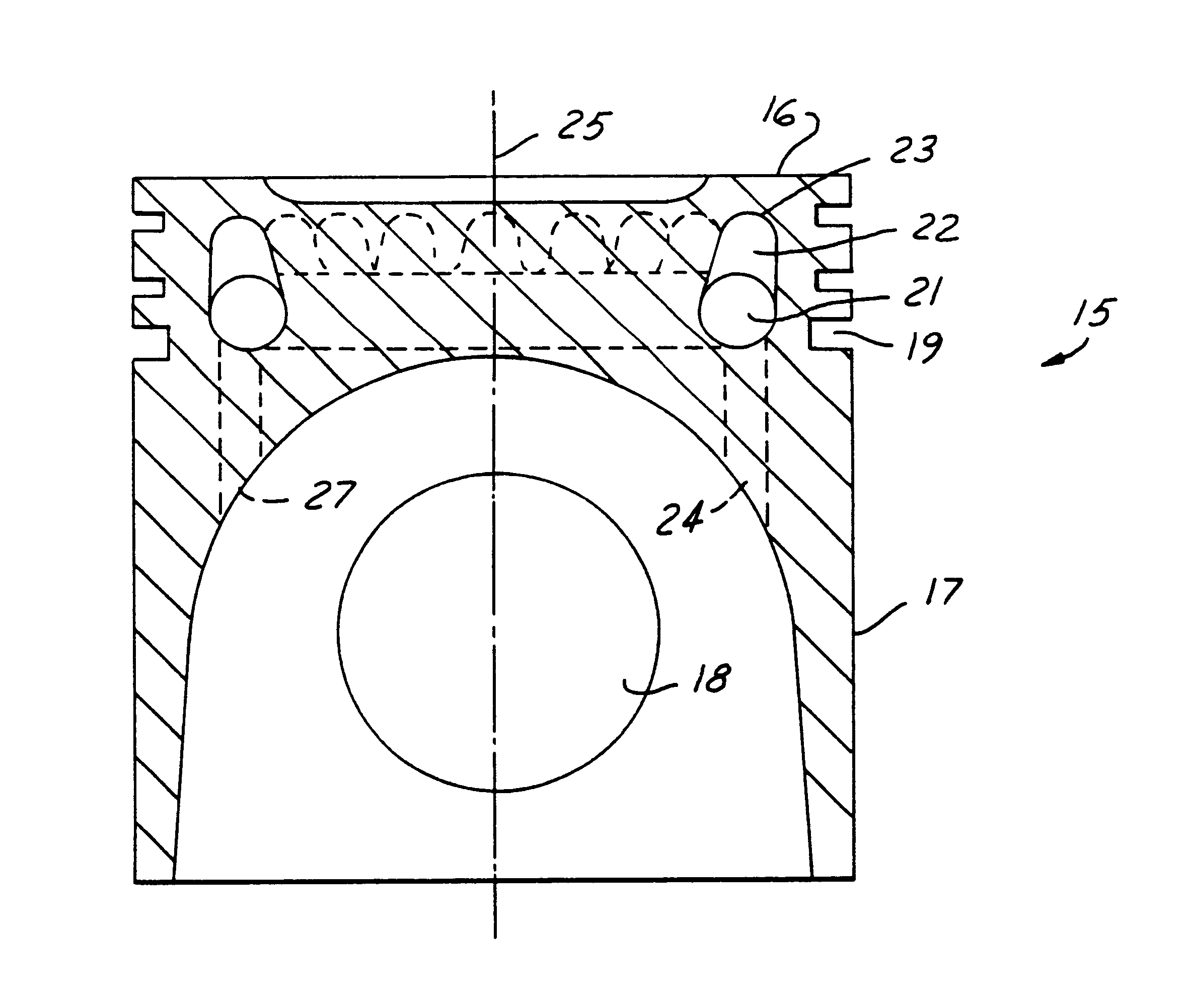
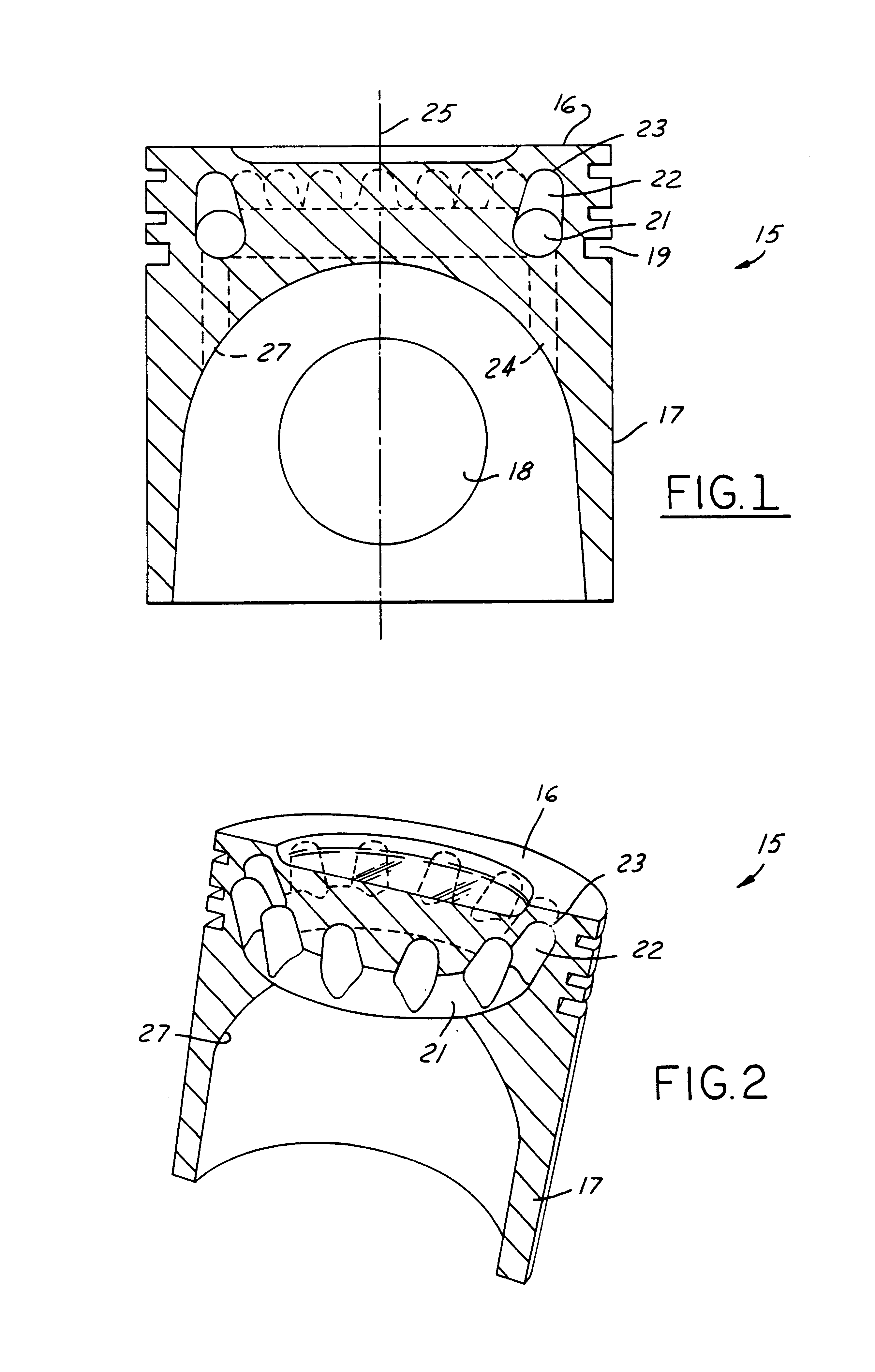
[0056]Referring to the drawing(s), and in particular FIG. 1, a (cast) piston 15, is of generally cylindrical form, with a hollow underside 27, to house the small end of a connecting rod (not shown), through a transverse pin 18. In a conventional piston, with a gudgeon or wrist pin, bearing is taken at the piston walls.

[0057]Alternatively, a spherically-jointed piston configuration (not shown), with a part-spherical bearing surface on the piston underside, interfacing with a complementary, part-spherical bearing surface upon a connecting rod small end, and located by a retaining ring, also with a part-spherical bearing surface, and fitted to the piston internal wall, is com...


PUM


Abstract

A cast piston, for an internal combustion engine or pump has an integral coolant ring gallery, with localized extensions, to achieve a coolant interchange with the gallery upon piston reciprocation. At least a portion of an extension lies generally parallel to the longitudinal piston axis and towards an upper end of the piston adjacent the working fluid. This provides an attendant increase in surface area exposed to coolant allowing either a decrease in operational piston temperature or an increase in allowable heat flow into the piston from a working fluid.

Description

TECHNICAL FIELD[0001]The present invention relates to cooling systems for piston mechanisms, and more particularly to pistons with coolant gallery configurations.BACKGROUND[0002]In a piston for a positive-displacement, reciprocating piston-in-cylinder device, such as an internal combustion engine prime mover or a pump, the (upper) part of the piston nearest the working fluid commonly incorporates a coolant gallery, for a coolant, or more specifically (fluid) heat transfer medium, typically a liquid, such as a lubricating oil. For a cast piston, such a coolant gallery can be integrally cast within it. This is typical of current aluminum alloy pistons for medium-duty diesel engines.[0003]In striving for (energy conversion and thermodynamic) efficiency, reduced emissions and enhanced “user satisfaction”, internal combustion engine design must balance conflicting requirements. The materials used in the construction of such engines are under severe stress and there is little margin betwe...

Claims


Application Information

Patent Timeline
Patent Type & Authority Patents(United States)
IPC IPC(8): F01B31/08F02F3/22
CPCB22C9/105F02F3/22F05C2201/0448F05C2201/021
Inventor WILKSCH, MARK CONRADFRANKLIN, PHILIP CLIVE
Owner SENECA TECH
Why Eureka
Try Eureka