Aircraft floor of optimized compactness

a technology of aircraft and compactness, applied in the direction of aircraft accessories, metal-working apparatuses, vehicle components, etc., can solve the problem that the mechanical properties of the crossmembers are not significantly modified

Active Publication Date: 2011-01-06
AIRBUS OPERATIONS (SAS)
View PDF40 Cites 30 Cited by
  • Summary
  • Abstract
  • Description
  • Claims
  • Application Information

AI Technical Summary

Benefits of technology

[0007]Thus, this arrangement does not significantly modify the mechanical properties of the crossmembers. In particular, each crossmember made up of top and bottom partial crossmembers presents substantially the same second moment of area as a conventional one-piece crossmember. This second moment of area comes from the relatively tall height that can be given to the crossmember made up of two partial crossmembers. In contrast, the space available between the top and bottom partial crossmembers is useful for housing members such as those mentioned above, instead of placing them under the floor. This results in more space being made free under the floor. It is thus possible to increase the volume available for a cargo zone, or on the contrary, by lowering the floor, to increase the volume available in the cabin. It is also possible to take advantage of this greater compactness to reduce the total section of the fuselage. Conversely, for unchanging compactness, it is possible to increase the total height of the crossmembers of the floor so as to enable the floor to contain systems that are more voluminous than those that have been associated with the floor in the prior art. Furthermore, systems may be put into place between the partial crossmembers before they are connected together to constitute the crossmembers. This makes it much easier to install such systems, and in particular makes installing them more ergonomic for operators.
[0009]That constitutes a simple way of fastening partial crossmembers together.
[0014]That constitutes a way of fastening the portions together that is simple to implement.
[0016]Thus, it is possible to begin by mounting the two lateral floor portions in the fuselage and to mount the middle portion only subsequently. After the lateral portions have been mounted, it is possible immediately and without waiting for the middle portion to be installed, to assemble systems in the so-called “triangular” zones. Access thereto when the middle portion is absent is easy and relatively ergonomic. In particular, operators can remain standing while they are installing systems. Furthermore, certain systems may be mounted on the middle portion of the floor before it is brought into the fuselage so as to be fastened to the lateral portions. Once more, conditions for mounting such systems are greatly improved, so far as the operators are concerned, since the middle portion is not yet installed in the fuselage. In addition, it is possible to assemble systems on the middle portion while the triangular zones of the fuselage are receiving the systems that are associated therewith. The corresponding operations can therefore be performed in parallel, thereby enabling the overall time required to build the aircraft to be reduced. Furthermore, the invention presents the additional advantage that the middle portion, which by definition has dimensions that are smaller than the overall dimensions of the floor, may be inserted even after the top portion of the fuselage segment has been secured to the bottom portion, such that the middle portion may no longer be inserted in the fuselage from the top. Since the middle portion is of small size, it is entirely possible to introduce the middle portion through the front or rear opening of the fuselage segment. In addition, the freedom thus provided for assembling the entire fuselage segment prior to inserting the middle portion of the floor makes the method of building the aircraft even more flexible, thereby also helping shorten the overall time required for assembly.
[0024]Thus, the essentially polluting operations (such as drilling holes) that are performed while making the floor portion are prevented from polluting the environment inside the fuselage. Conversely, operations performed previously on the fuselage will not pollute the floor portion.

Problems solved by technology

Thus, this arrangement does not significantly modify the mechanical properties of the crossmembers.

Method used


Image

  • Aircraft floor of optimized compactness
  • Aircraft floor of optimized compactness
  • Aircraft floor of optimized compactness

Examples


Embodiment Construction

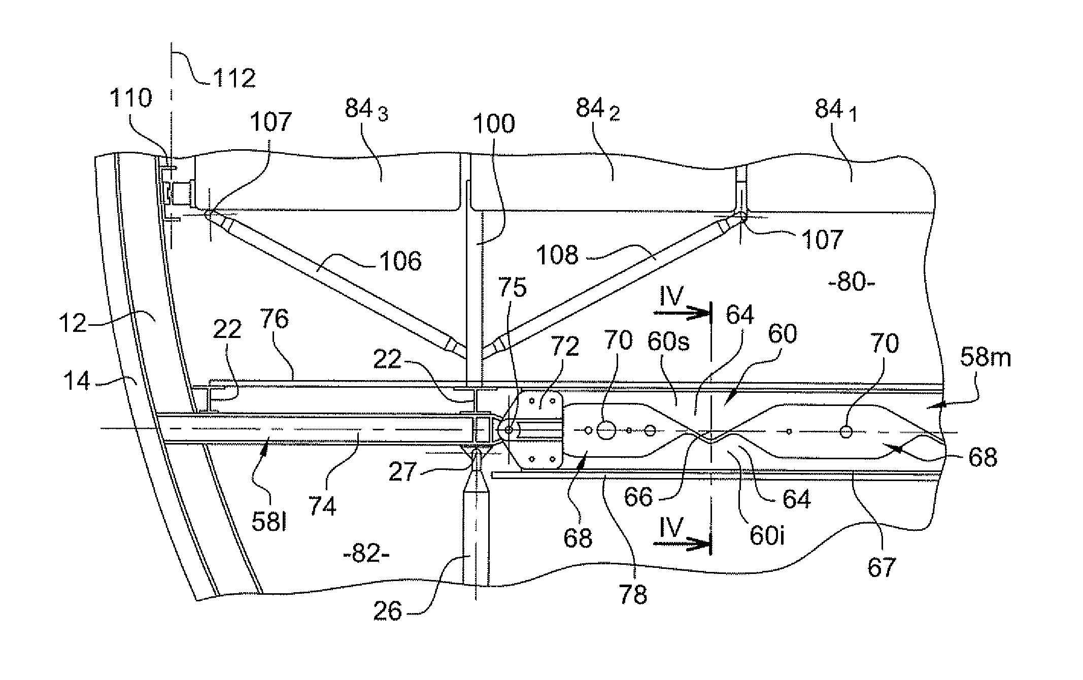
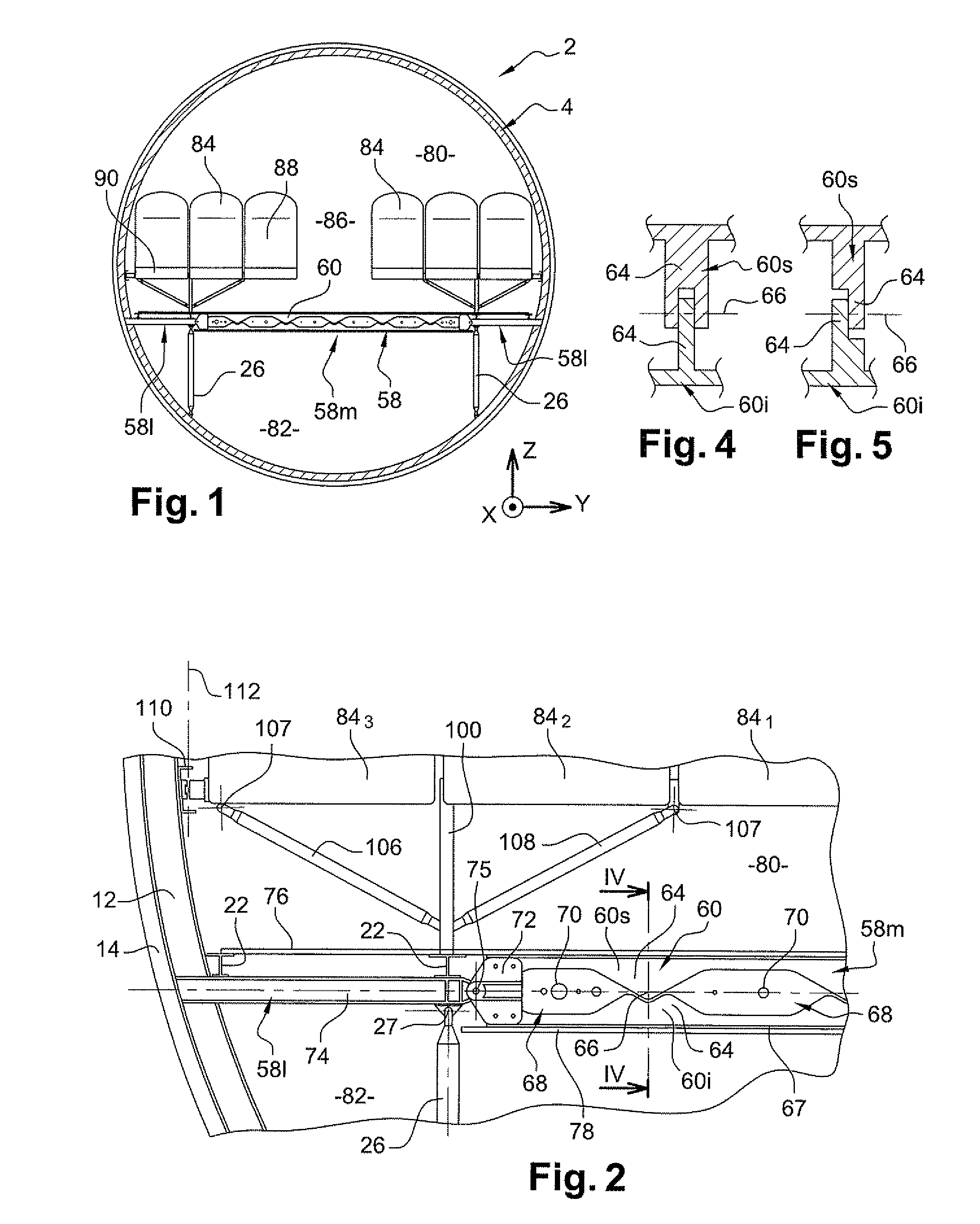
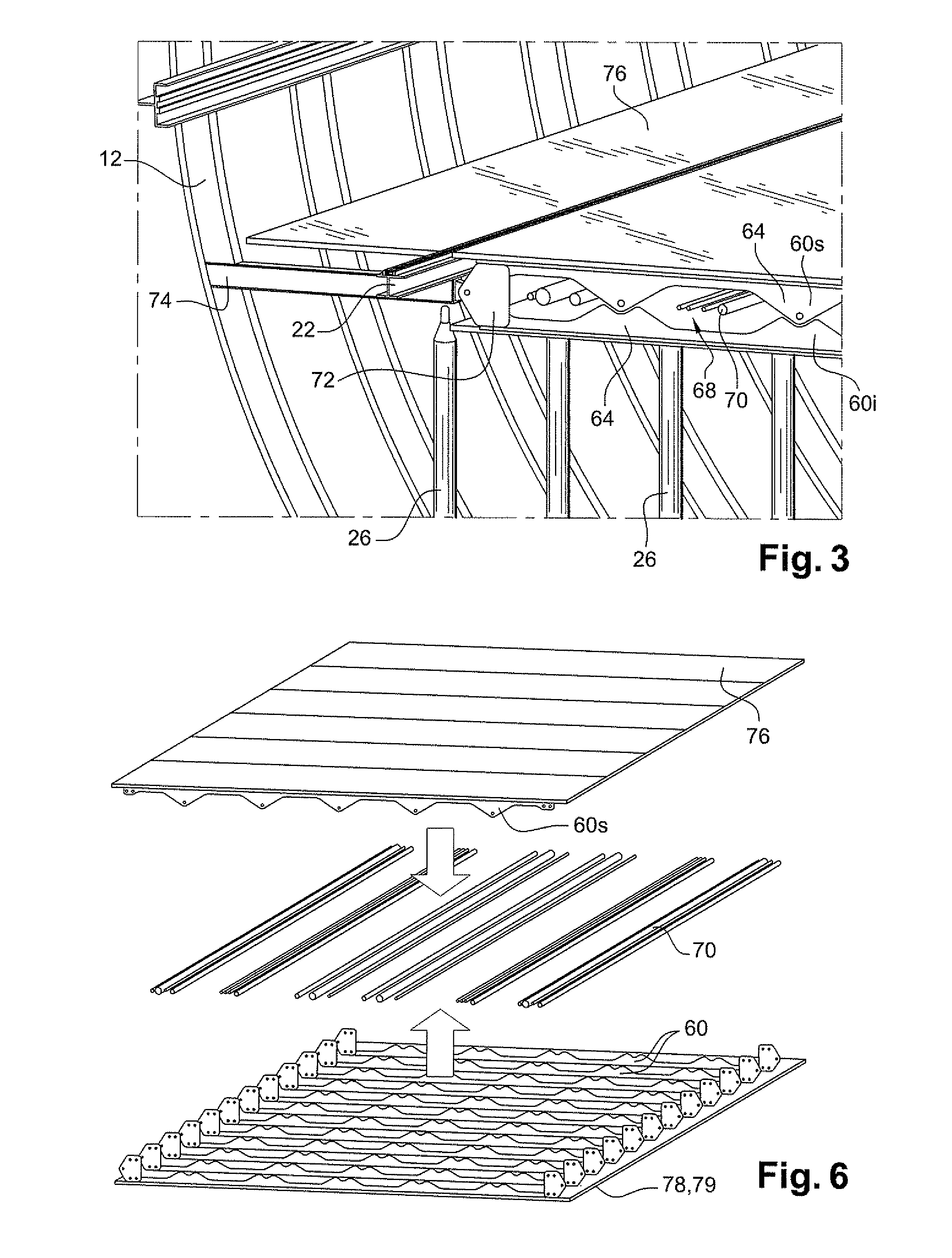
[0037]With reference to FIG. 1, the aircraft 2 of the invention in the embodiment described below is constituted by an aerodyne, and specifically an airplane. The airplane has a fuselage 4, two wings, a tail, and engines, specifically two engines fastened to the wings in this example. An X, Y, and Z frame of reference is used below in which the direction X designates the longitudinal horizontal direction of the fuselage, the direction Y designates the horizontal direction perpendicular to the direction X, and the direction Z designates the vertical direction.

[0038]Over the major fraction of its length, the fuselage presents a generally cylindrical shape of axis parallel to the direction X, and of section that is generally circular in a plane perpendicular to said direction. A segment of the fuselage is shown in FIGS. 1 to 3 and 7. The description below relates to this segment, it being understood that the fuselage may comprise a plurality of segments made up in the same manner and l...


PUM

PropertyMeasurementUnit
heightaaaaaaaaaa
heightaaaaaaaaaa
heightaaaaaaaaaa

Abstract

An aircraft floor portion includes crossmembers. Each crossmember comprises a top partial crossmember and a bottom crossmember, with at least one gap being left between the top partial crossmember and the bottom partial crossmember of each crossmember.

Description

[0001]The invention relates to aircraft, and in particular to their floors.BACKGROUND OF THE INVENTION[0002]It is known to make an airplane floor using horizontal crossmembers that extend perpendicularly to the longitudinal direction of the fuselage. Longitudinal rails are fastened on the crossmembers, and in turn they are covered by a floor panel. The rails support the passenger seats.[0003]Numerous systems or members generally need to be fastened to the floor. For example, these may be hydraulic or pneumatic members (compressed air or air conditioning ducts, water ducts, refrigeration ducts, oxygen ducts), electric cables, fire extinguisher circuit elements, or indeed cables of on-board communications networks. These various members are generally located under the crossmembers of the floor. A covering panel masks and protects these members relative to a cargo zone.[0004]The drawback of that arrangement is that it occupies a considerable amount of height, thereby penalizing the hei...

Claims


Application Information

Patent Timeline
Patent Type & Authority Applications(United States)
IPC IPC(8): B64C1/18B21D53/88
CPCY10T29/49622B64C1/18
Inventor DELAHAYE, ROMAINGALLANT, GUILLAUMEEVE, OLIVIER
Owner AIRBUS OPERATIONS (SAS)
Why Eureka
Try Eureka