Reciprocating pump

a reciprocating pump and pump body technology, applied in the direction of machines/engines, liquid fuel engines, positive displacement liquid engines, etc., can solve the problems of unsuitable downsizing and the above-described reciprocating pump disclosed, and achieve the effect of reducing the distance between the cylinders and facilitating assembly

Inactive Publication Date: 2009-05-14
MARUYAMA MFG CO INC
View PDF9 Cites 29 Cited by
  • Summary
  • Abstract
  • Description
  • Claims
  • Application Information

AI Technical Summary

Benefits of technology

[0010]As configured as above, the seal case may be sandwiched between the front metal fitting and the base metal fitting by means of the front metal fitting provided at the small diameter section at the front end side of the seal case and the base metal fitting provided at the back end side of the seal case and is coupled to a position rearward of the front metal fitting by means of a bolt which is provided at a position outside the seal case except the portions between the cylinder sections and extends in the axial direction of the cylinder section. Therefore, the cylinder distance can be reduced in comparison with the conventional distance while maintaining the thickness between cylinders, downsizing can be achieved in a direction of the cylinder sections arranged in parallel, and the assembling is facilitated.

Problems solved by technology

However, the above described reciprocating pump disclosed in the Patent Document is not suitable for downsizing since an individual sleeve having a cylinder therein has a male screw on an outer peripheral thereof, and is threaded into a holder member to form a triple pump chamber, which requires a thickness required to withstand the pressure between the three chambers as well as a thickness necessary for thread formation.

Method used


Image

  • Reciprocating pump
  • Reciprocating pump
  • Reciprocating pump

Examples


Embodiment Construction

[0016]Hereinafter, embodiments of the present invention will be described with reference to the accompanying drawings. It should be noted that in the description of the drawings, like reference characters refer to like elements and the duplicate description is omitted. Moreover, unless otherwise indicated, a vertical direction indicates the direction in the explanatory drawing.

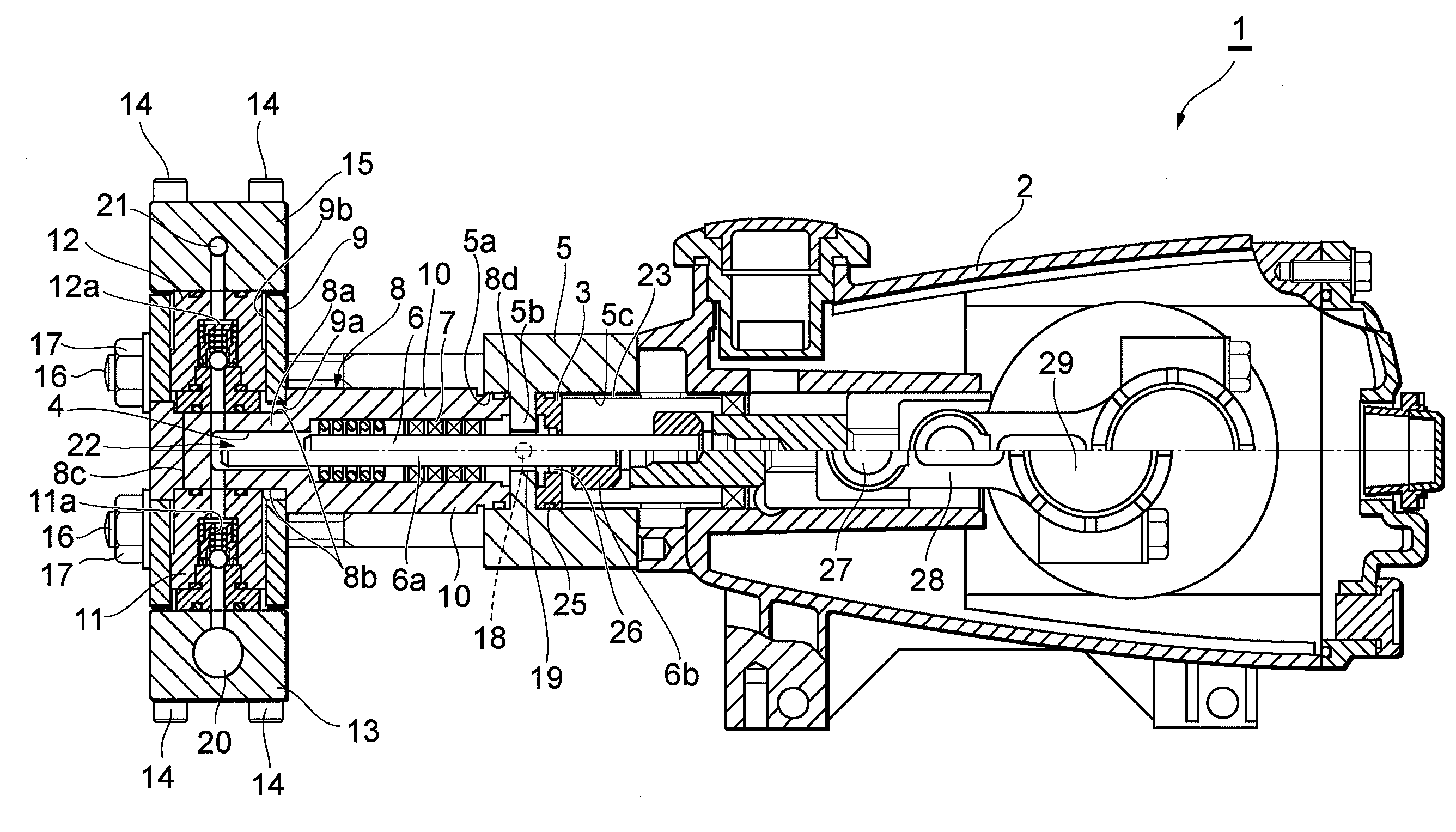
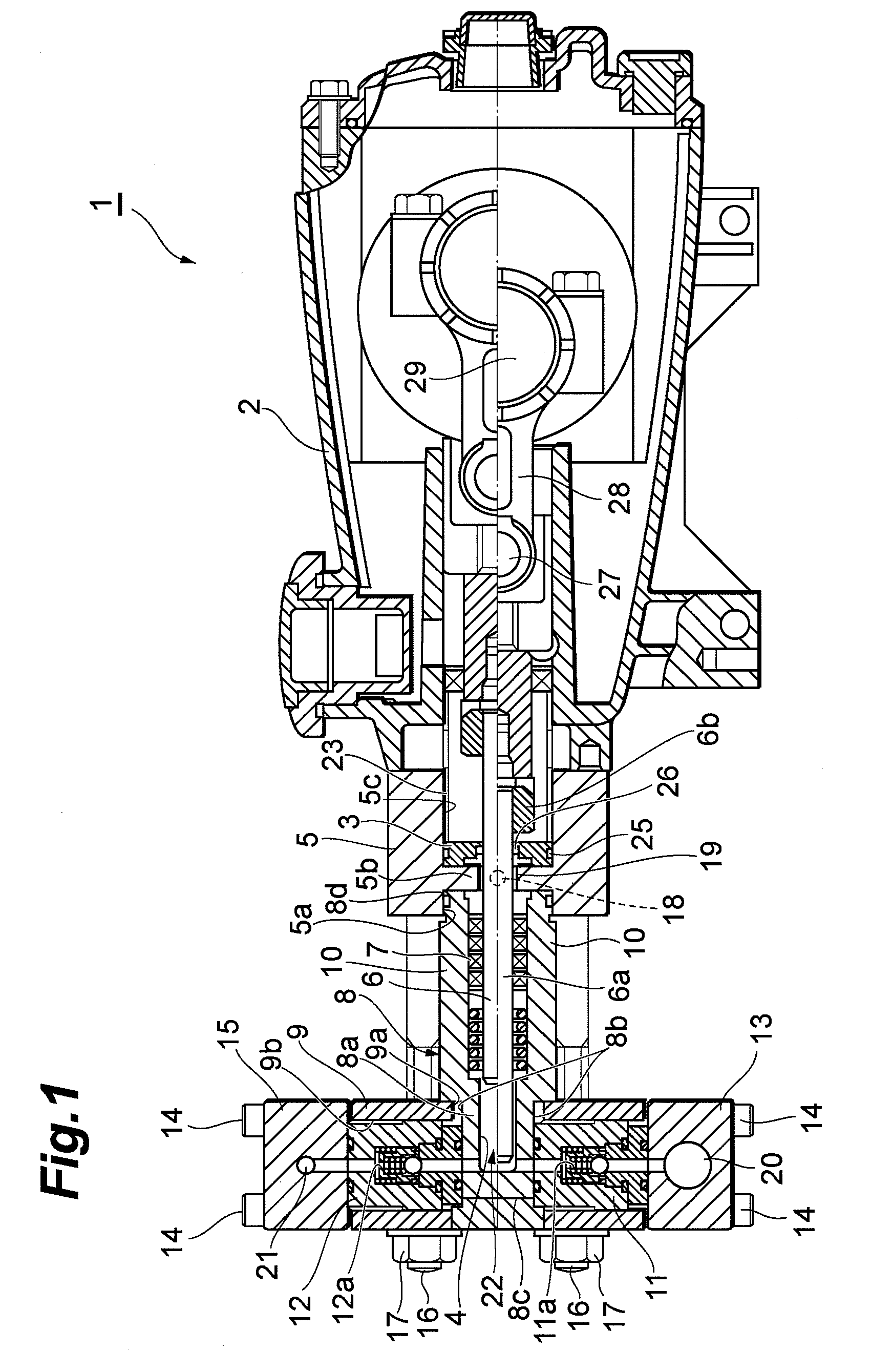
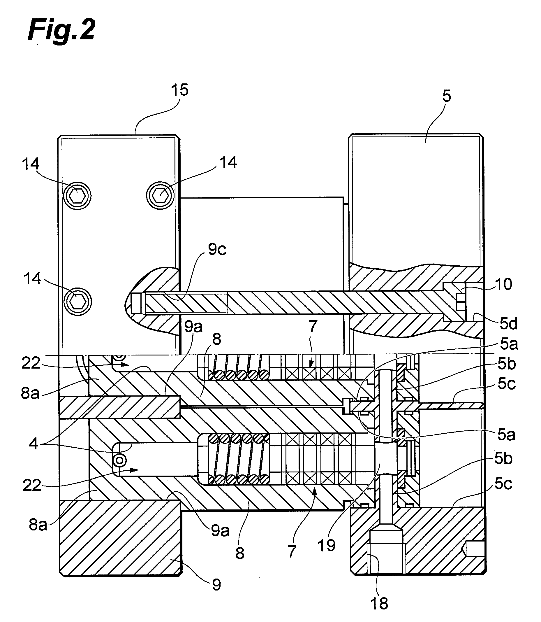
[0017]FIG. 1 is a longitudinal sectional view illustrating a reciprocating pump in accordance with an embodiment of the present invention; FIG. 2 is a partial sectional plan view of a front end of the reciprocating pump illustrated in FIG. 1; and FIG. 3 is a partial sectional front view of the reciprocating pump illustrated in FIG. 1. It should be noted that the upper side portion of the center line of a reciprocating member 6 illustrated in FIG. 1 indicates the reciprocating member 6 positioned at the bottom dead center, and the lower side portion thereof indicates the reciprocating member 6 positioned at the...


PUM


Abstract

The reciprocating pump for performing a pumping action by reciprocating an individual reciprocating member inside a plurality of cylinder sections arranged in parallel includes a seal case in which a cylinder section is formed and which functions as an independent pressure-resistant container; and a suction valve and a discharge valve in which a valve chamber is formed individually and each of which functions as an independent pressure-resistant container. The suction valve and the discharge valve are coupled so as to sandwich two planar sections from a direction perpendicular to a direction in which a plurality of cylinder sections are arranged in parallel in a state in which each of the suction valve and the discharge valve abuts against the respective one of the two planar sections of an external surface of a small diameter section at a front end side formed in the seal case, and the valve chamber is communicatively connected to the cylinder section. Thereby, the cylinder distance can be reduced while maintaining the thickness between cylinders and the assembling is facilitated.

Description

BACKGROUND OF THE INVENTION[0001]1. Field of the Invention[0002]The present invention relates to a reciprocating pump.[0003]2. Related Background Art[0004]Conventionally, as a reciprocating pump for pumping a liquid, there has been known a reciprocating pump having a plurality of pump chambers capable of applying a high pressure to a fluid (for example, see Japanese Patent No. 3423915). The reciprocating pump disclosed in the Patent Document is a triple plunger pump having three pump chambers and an individual plunger has a sleeve with a pump chamber formed therein. The sleeve is formed as an independent arrangement separated from the reciprocating pump body. The front end side thereof is connected to a valve body through a high pressure pipe joint and the back end side thereof is screw-fastened to a holder member. The holder member is bolt-attached to a crankcase of the reciprocating pump.SUMMARY OF THE INVENTION[0005]However, the above described reciprocating pump disclosed in the...

Claims


Application Information

Patent Timeline
Patent Type & Authority Applications(United States)
IPC IPC(8): F04B1/26
CPCF04B39/14F04B53/22F04B53/143F04B53/007
Inventor OHNISHI, TOSHIAKI
Owner MARUYAMA MFG CO INC
Why Eureka
Try Eureka