[0011]An
antenna design in accordance with the invention thus enables it to be fully integrated into a
mobile device which has
wireless data transmission. Because of its small dimensions and the flexibility of its geometric
layout, the antenna structure in accordance with the invention can then be integrated into a plastic housing. It is thus possible to design an antenna which is completely invisible from outside. It should further be emphasized that on its feed points, an antenna in accordance with the invention has essentially symmetrical electrical characteristics in relation to a fixed
external reference potential. The feed to the antenna can have a symmetrical
layout, enabling interference in a receiving section to be reduced. An antenna
layout in accordance with the invention also enables the antenna structure to be realized as a
slot antenna in a
metal surface. This is possible because of the duality principle, and allows the maximum possible flexibility in the design of an antenna.
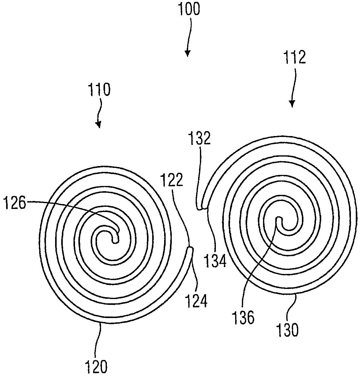
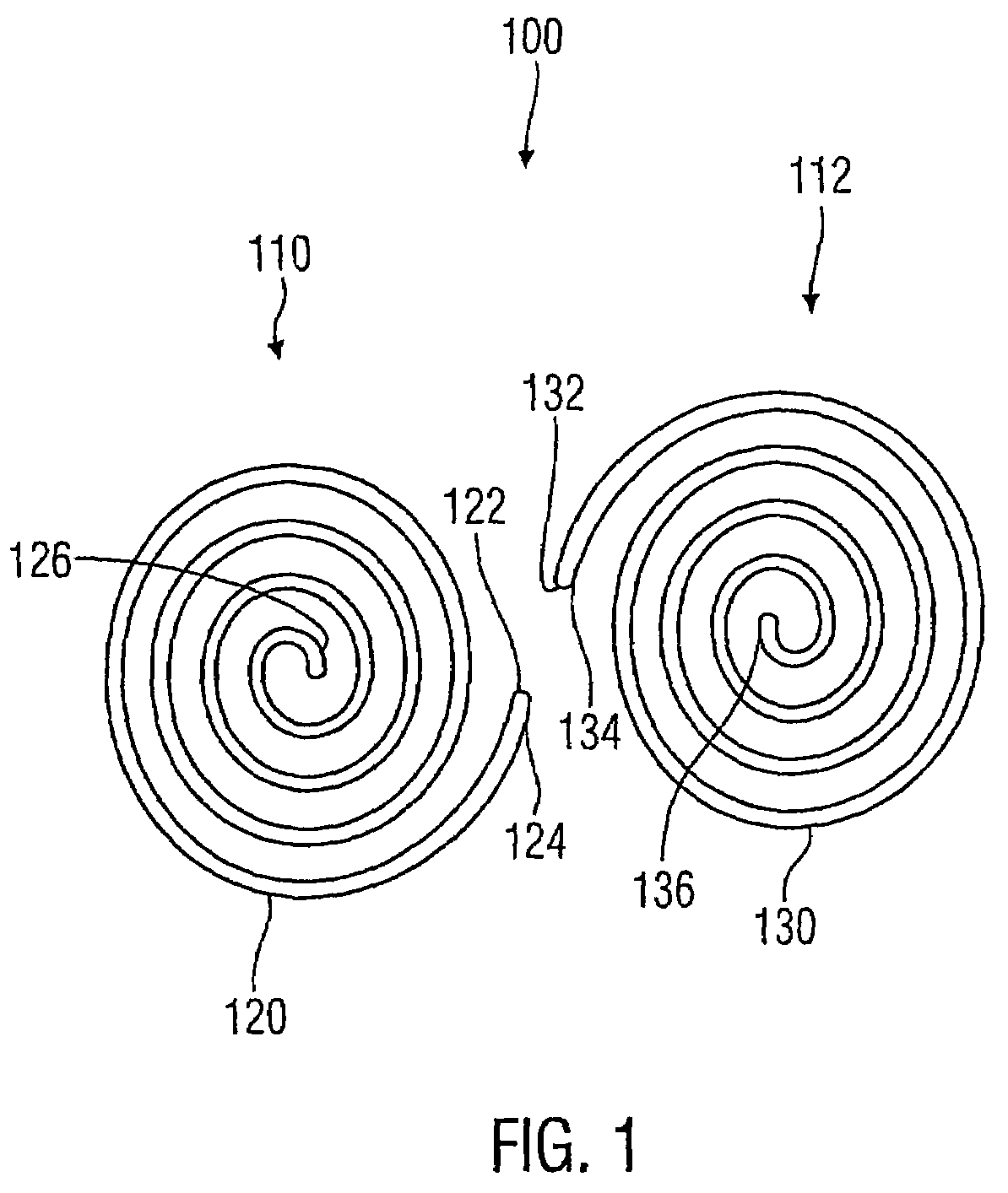
[0012]In a preferred form of embodiment of the antenna in accordance with the invention, the gap between the first
feed point and the second
feed point is at least 0.005 times the freespace
wavelength at an
operating frequency for which the antenna is designed. Such a gap between the feed points ensures that the
input impedance of the antenna lies in a technically advantageous range, so that
impedance matching can be effected by simple means. Furthermore, a gap between the feed points of more than 5*10−3 times the freespace
wavelength ensures good reproducibility of the antenna structure.
[0018]It is further preferred that the design of the antenna is such that in relation to a reference potential it has essentially symmetrical electrical behavior at the first feed point and the second feed point. This enables the antenna to be fed symmetrically and, by comparison with asymmetric antennas, renders superfluous a large reference potential area. It is advantageous to avoid an extended reference potential area, in particular for very small devices, because in this case their dimensions are smaller than the
wavelength of the transmission frequencies used, and because such devices often have no large metallic or metallized housing components.
[0019]It is further preferred that the first radiator and the second radiator are formed on the surface of a
dielectric material. Namely, because it has been found that applying an antenna structure in accordance with the invention onto a
dielectric substrate does not significantly degrade the antenna characteristics. The use of a substrate is advantageous because this not only improves the mechanical robustness of the antenna compared to a self-supporting metallized structure, but also makes manufacture easier. Namely because it is then possible, for example, to apply the metallic structures onto the surface of the
dielectric material by a
coating process (e.g. vapor deposition, lamination, bonding), followed by structuring them. So it is unnecessary to manufacture separately a metallized structure, which would be very difficult to
handle and lacking in mechanical robustness.
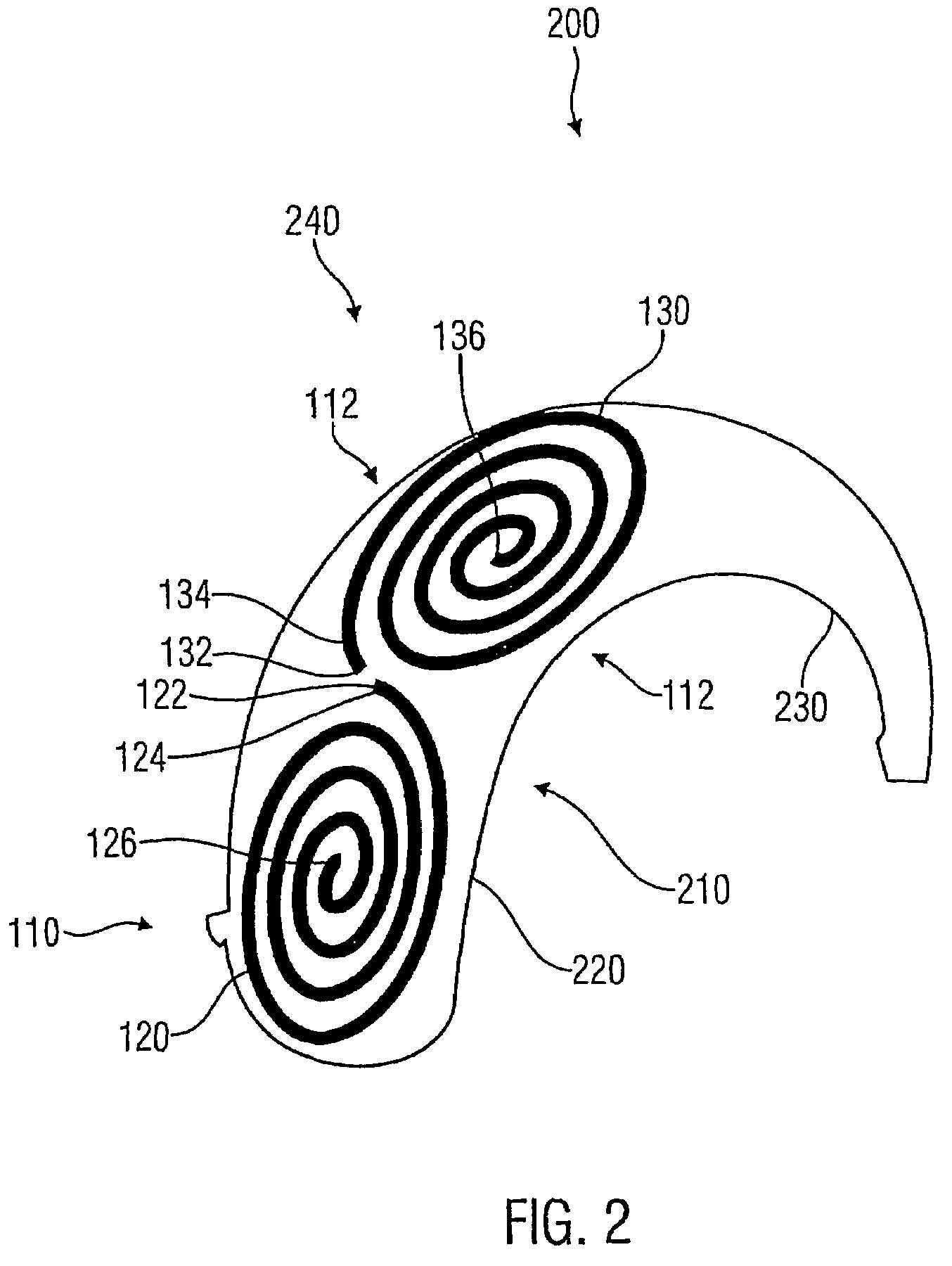
[0021]Apart from this, it is advantageous to integrate the first radiator and the second radiator into the housing of an electronic device which is made of a dielectric material and which houses an electric circuit. It is, indeed, not only possible to apply the antenna structure in accordance with the invention to the surface of a
dielectric substrate, but it is also possible to integrate it into the substrate, i.e. the housing. Such a design can bring very major advantages with many applications, firstly because it protects the antenna against external influences and damage, and secondly because the antenna is no longer visible from outside. The
radiation characteristics of the antenna are not significantly degraded if the housing is thin enough.
[0022]It has further been found that the antenna in accordance with the invention can with
advantage be arranged on the surface of a housing which is part of a behind-the-ear
hearing aid. Such a behind-the-ear hearing aid is typically designed to be worn behind the pinna of a person's ear. It has been found that the
adaptation and
radiation characteristics of an antenna in accordance with the invention are good even in this difficult
operating environment.

