High pressure steam water injector comprising an axial drain

a technology of injector and axial drain, which is applied in the direction of mixer, steam boiler components, reactor fuel elements, etc., can solve the problems of difficult design of devices, insufficient performance of injector prototypes, and unreliable use of injectors in nuclear reactors

Inactive Publication Date: 2003-07-22
COMMISSARIAT A LENERGIE ATOMIQUE ET AUX ENERGIES ALTERNATIVES
View PDF15 Cites 28 Cited by
  • Summary
  • Abstract
  • Description
  • Claims
  • Application Information

AI Technical Summary

Benefits of technology

In addition, it can be easily understood that the axial drain 10 also makes it possible to reduce the section of the flow passageway at the neck 5, between the mixing chamber 4 and the diffuser 7, and hence makes it possible to increase the maximum pressure of the flow at outlet 8, compared with the case in which said axial drain is not used with the same diffuser. It is generally admitted that the increase in pressure is practically conversely proportional to the section of the passageway at neck 5.

Problems solved by technology

These devices are difficult to design on account of their revolving parts and some depend upon electric sources.
Up until now, the different injector prototypes put forward have been found to perform insufficiently and to be unreliable for use in nuclear reactors.
This start-up may also be difficult to achieve as the drain must be properly positioned.
However, reducing the size of this section renders start-up of the device even more difficult.
The complex functioning and loss of water from this type of steam injector have meant that it could not be chosen for nuclear reactor installations.

Method used


Image

  • High pressure steam water injector comprising an axial drain
  • High pressure steam water injector comprising an axial drain
  • High pressure steam water injector comprising an axial drain

Examples


Embodiment Construction

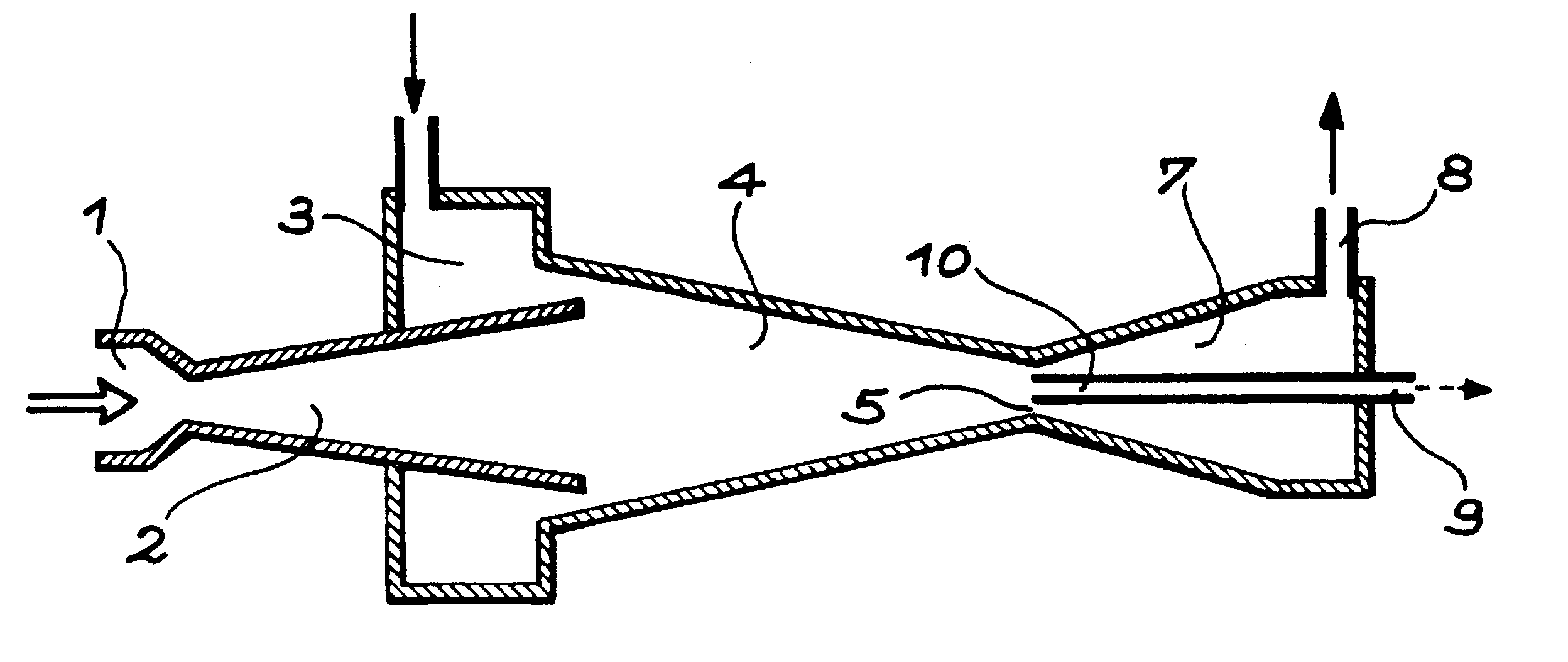
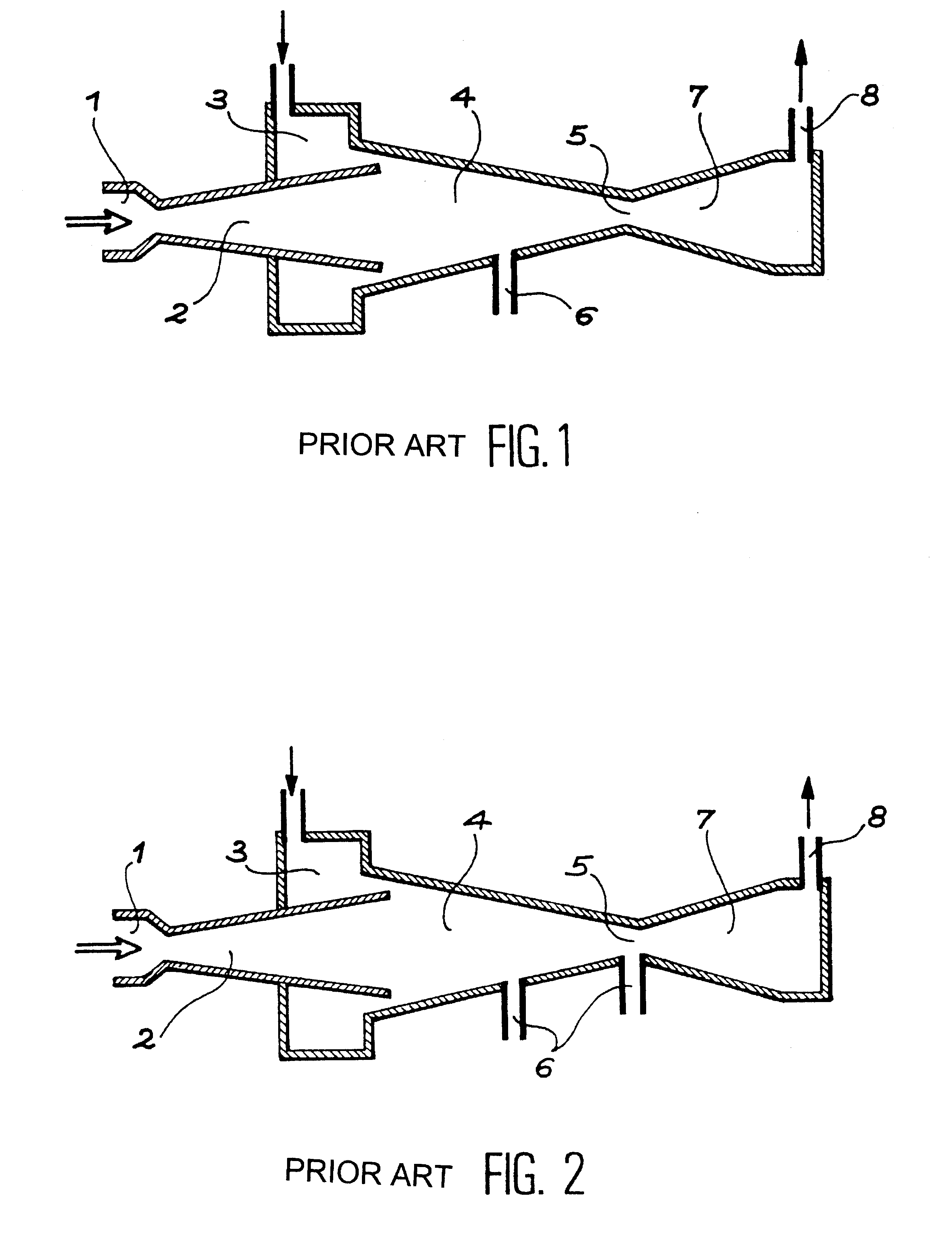
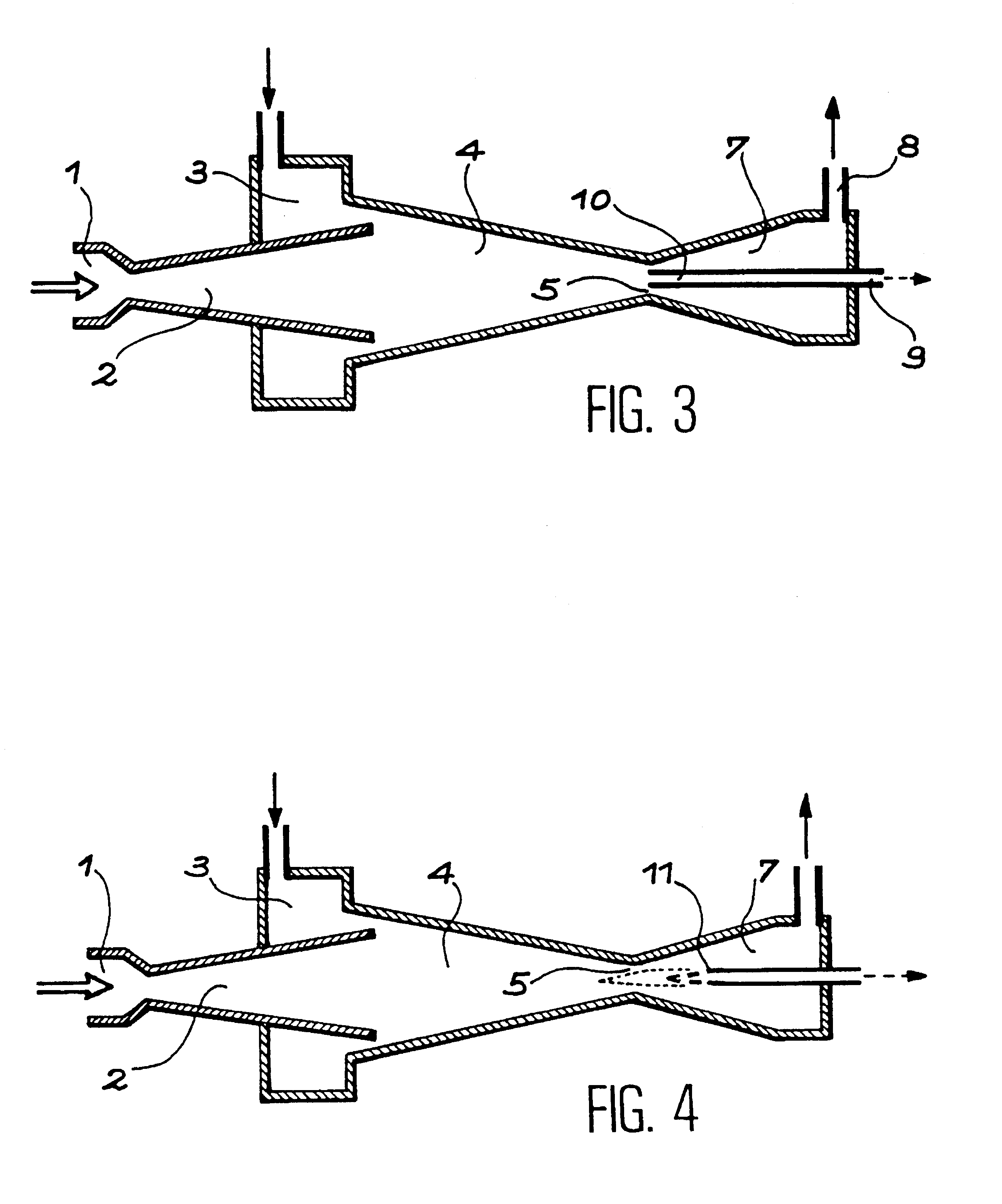
With reference to FIG. 3, the injector of the invention reproduces the main parts of the steam injector of the prior art described with reference to FIG. 1, with the exception of the side evacuation drain 6. There is therefore a steam inlet 1 leading into a Laval nozzle 2, a ring-shaped entry chamber 3 leading into the mixing chamber 4, positioned at the outlet of nozzle 2 and ending in neck 5. A diffuser 7 is placed at the exit of the neck leading into an outlet 8. At the neck 5, an axial drain 10 is positioned that is formed of an evacuation duct and extends across diffuser 7 and ends on the outside 9, outside the steam injector that is the subject of this application. It has been shown that diphase flow remains essentially annular as far as the neck, the film of water being flattened against the wall of this mixing chamber 4. This experimental fact contradicts previously accepted knowledge, namely the more or less rapid spraying of the aspirated film of water. Said axial drain 10...


PUM


Abstract

The steam injector is characteristic in its high pressure and improved start-up. It uses an axial drain (10) positioned in the centre of the neck (5) downstream from the mixing chamber (4) and inserted in the diffuser (7) for the purpose of narrowing the section of the neck (5) and evacuating a large part of the steam which has not been condensed. The axial drain (10) may be mounted so that it is axially mobile.Application to the water supply for steam generators in pressurized water nuclear reactors.

Description

The invention relates to the area of high pressure injectors, intended to inject water into a machine or installation containing a pressurized reservoir. Generally, the latter is the steam production tank of a steam boiler. This is the case in particular for steam generators used in nuclear reactors, especially pressurized water reactors. However, the use of this type of injector could be applied to any type of steam-producing reservoir using part of this steam as driving energy source and a low pressure reservoir as water source.PRIOR ART AND PROBLEM RAISEDFor over a century the use of steam injectors has been known (see GIFFARD patent in 1850), in particular for steam engines such as locomotives and ships. Nowadays, these devices are especially used in industrial installations requiring the decanting of solutions or liquid waste likely to rapidly deteriorate conventional pumping systems. In water nuclear reactors, the use of injectors as an emergency supply has been examined. Such...

Claims


Application Information

Patent Timeline
Patent Type & Authority Patents(United States)
IPC IPC(8): F04F5/46F04F5/00F04F5/24F04F5/44
CPCF04F5/461Y10T137/87652
Inventor DUMAZ, PATRICKDUC, BERTRAND
Owner COMMISSARIAT A LENERGIE ATOMIQUE ET AUX ENERGIES ALTERNATIVES
Why Eureka
Try Eureka