Valve element for supplementary control valve device

a valve element and valve device technology, applied in the direction of mechanical equipment, machines/engines, manufacturing tools, etc., can solve the problems of relative high tool force and relatively rapid wear of tools, and achieve the effect of short switching time and very largely avoided high tool for

Inactive Publication Date: 2005-11-29
CONTINENTAL AUTOMOTIVE GMBH
View PDF12 Cites 23 Cited by
  • Summary
  • Abstract
  • Description
  • Claims
  • Application Information

AI Technical Summary

Benefits of technology

[0003]The invention is therefore based on the object of providing a valve element for a supplementary control valve device which can be produced essentially by cold forming in large-scale manufacture, in which case relatively high tool forces can very largely be avoided. Furthermore, the intention is to achieve relatively short switching times with the valve element.

Problems solved by technology

However, with this valve element it is disadvantageous that relatively high tool forces are required in large-scale manufacture by cold extrusion, particularly in the region of the thin wall thicknesses which are necessary, which brings about relatively rapid wear of the tools.

Method used


Image

  • Valve element for supplementary control valve device
  • Valve element for supplementary control valve device
  • Valve element for supplementary control valve device

Examples


Embodiment Construction

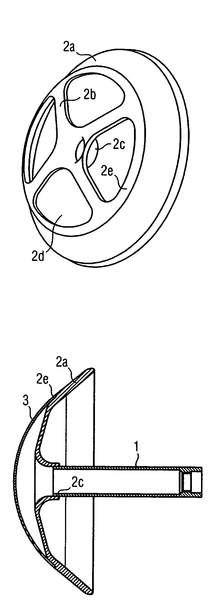
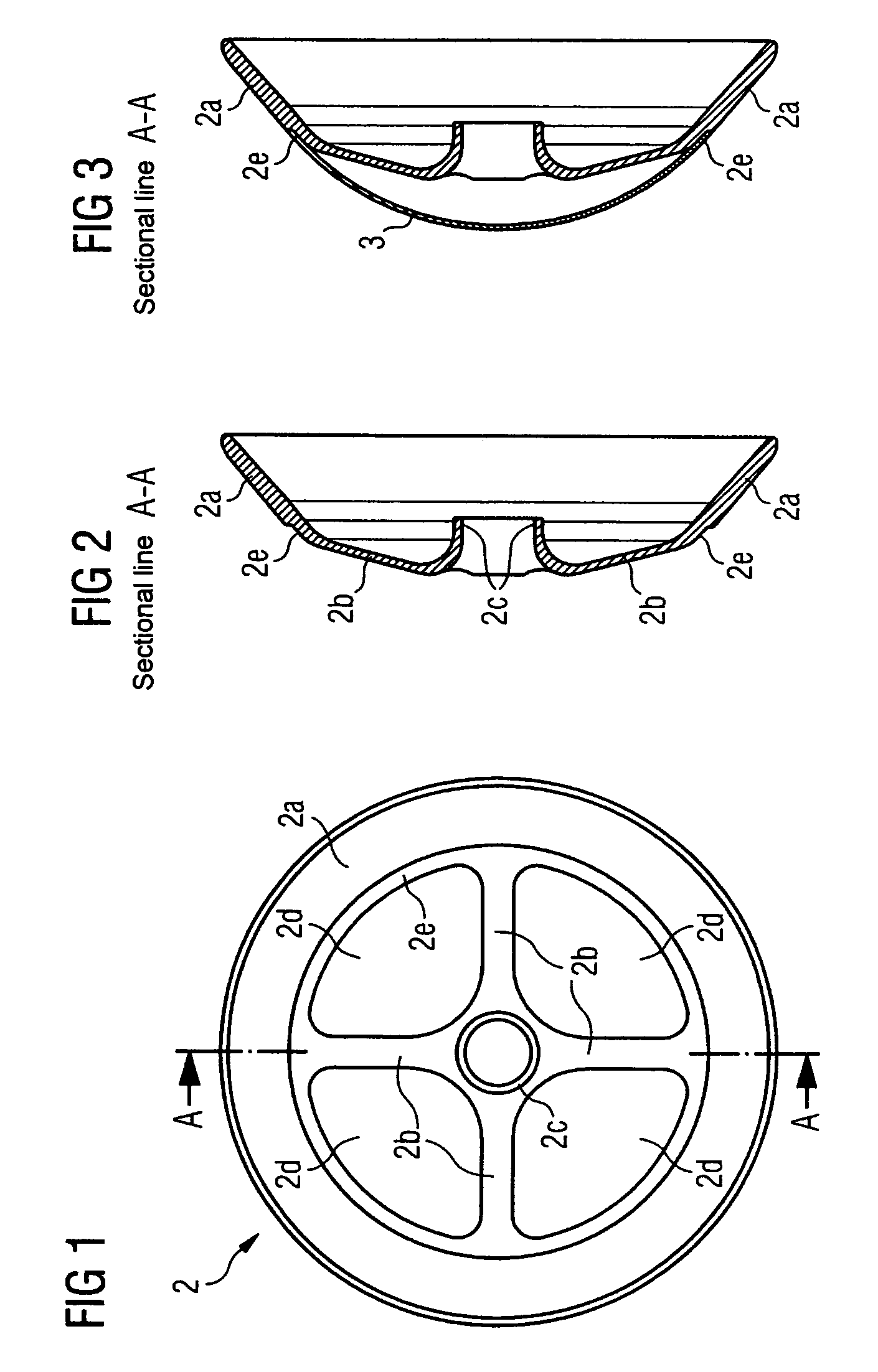
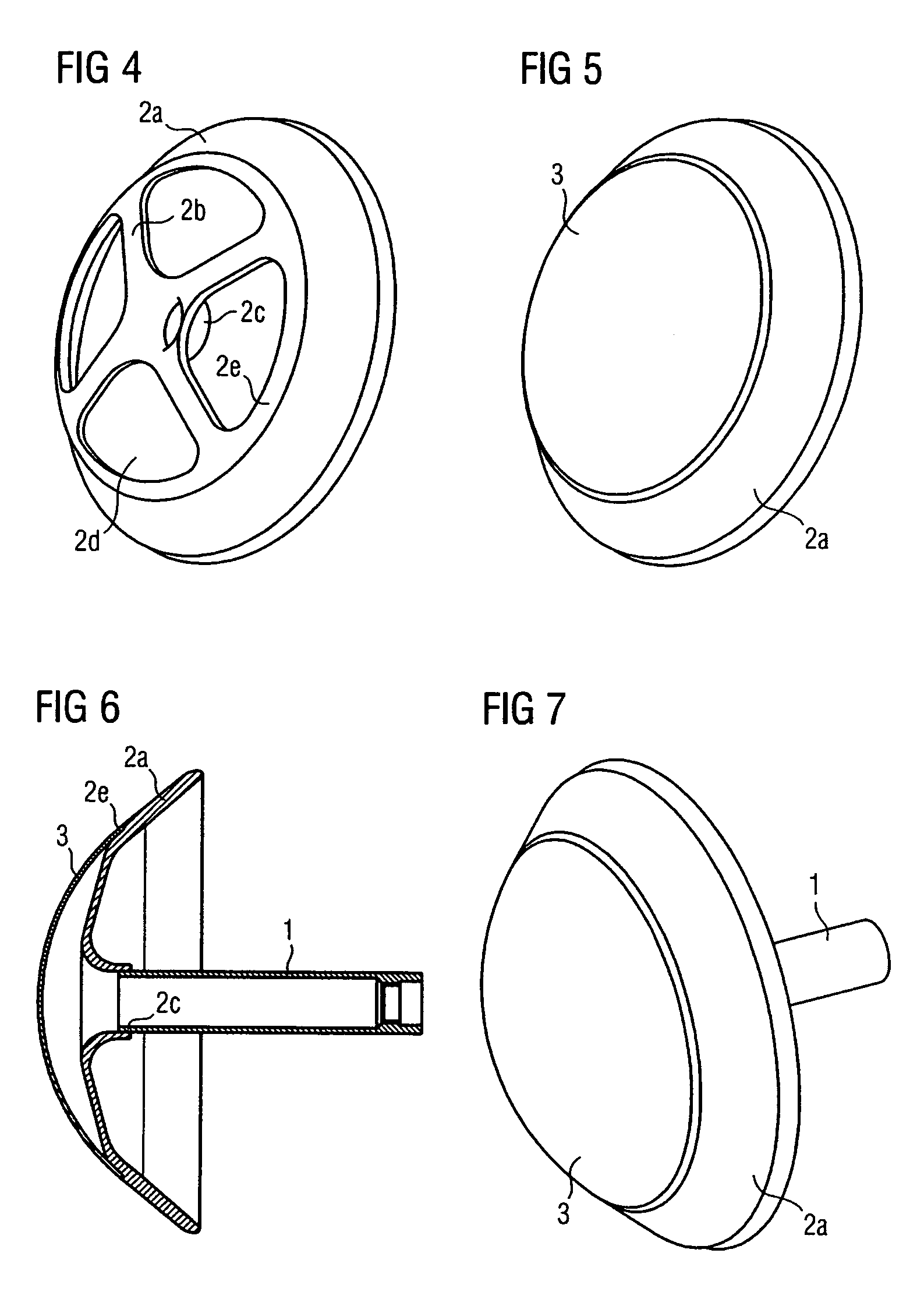
[0020]FIG. 1 is a plan view of the valve head 2 of the valve element. The valve head 2 has a continuously annular region 2a on the outside. Said region 2a is in the form of a circular ring in a plan view. Four cutouts 2d, which are of the same shape, are arranged between the annular region 2a and a central connection point 2c for connecting to the valve stem (not illustrated). Said cutouts 2d are each separated from one another by webs 2b. For reasons of clarity the at least one closure part has not been represented. A circumferential groove 2e is arranged on the inner boundary of the annular region. Said groove 2e has the purpose of securing the closure part (not illustrated).

[0021]FIG. 2 illustrates the valve head in cross section along the sectional line A—A in FIG. 1. The groove 2e is in the shape of a depression and is embodied in the form of a step in cross section.

[0022]FIG. 3 illustrates the valve head once more in cross section in a way which is analogous to FIG. 2, but add...


PUM

PropertyMeasurementUnit
widthaaaaaaaaaa
widthaaaaaaaaaa
shapeaaaaaaaaaa

Abstract

The valve element is composed of a valve stem, at one of whose ends a valve head is arranged, said valve head being of concave design in the direction of the valve stem, having on the outside a continuous annular region and having at least two cutouts between the annular region and the central connection point for connecting to the valve stem which are closed off by at least one closure part.

Description

CROSS REFERENCE TO RELATED APPLICATIONS[0001]The present application is a continuation of international application PCT / EP2004 / 050949, filed May 27, 2004 and designated the United States, and further claims priority to German patent application 10327271.2, filed Jun. 17, 2003, the both of which are herein incorporated by reference.BACKGROUND OF THE INVENTION[0002]The invention relates to a valve element for a supplementary control valve device. Valve elements for supplementary control valve devices are known. DE 101 37 828 A1 describes a supplementary control valve device which is arranged in an inlet duct of a piston internal combustion engine. In this supplementary control valve device there is provision for a valve element to be arranged which is of essentially mushroom-shaped design. In this valve element, a hat-shaped head, which is designed so as to be convex with an apex point on the side facing away from the inlet valve, is arranged on a stem. The natural frequency of the sy...

Claims


Application Information

Patent Timeline
Patent Type & Authority Patents(United States)
IPC IPC(8): F02B27/02F02B29/02F02B29/08F02D9/12F16K1/36
CPCF02B29/083F02D9/12F16K1/36Y02T10/146Y02T10/12
Inventor COLIC, RAJKOHANNEWALD, THOMASMANN, THOMASSEVERIEN, HERBERT
Owner CONTINENTAL AUTOMOTIVE GMBH
Why Eureka
Try Eureka