Cognitive radio system

a radio system and radio technology, applied in the field of cognitive radio systems, can solve the problems of a large amount of information which cannot be obtained and the use-state is hardly known by a wireless terminal device alon

Active Publication Date: 2007-11-01
KK TOSHIBA
View PDF22 Cites 200 Cited by
  • Summary
  • Abstract
  • Description
  • Claims
  • Application Information

AI Technical Summary

Problems solved by technology

However, there are a lot of information which cannot be obtained by a wireless terminal device alone, such as wireless-channel use-states of radio astronomy and a television receiver which perform only reception.
However, such use-states are hardly known by a wireless terminal device alone.

Method used


Image

  • Cognitive radio system
  • Cognitive radio system
  • Cognitive radio system

Examples


first embodiment

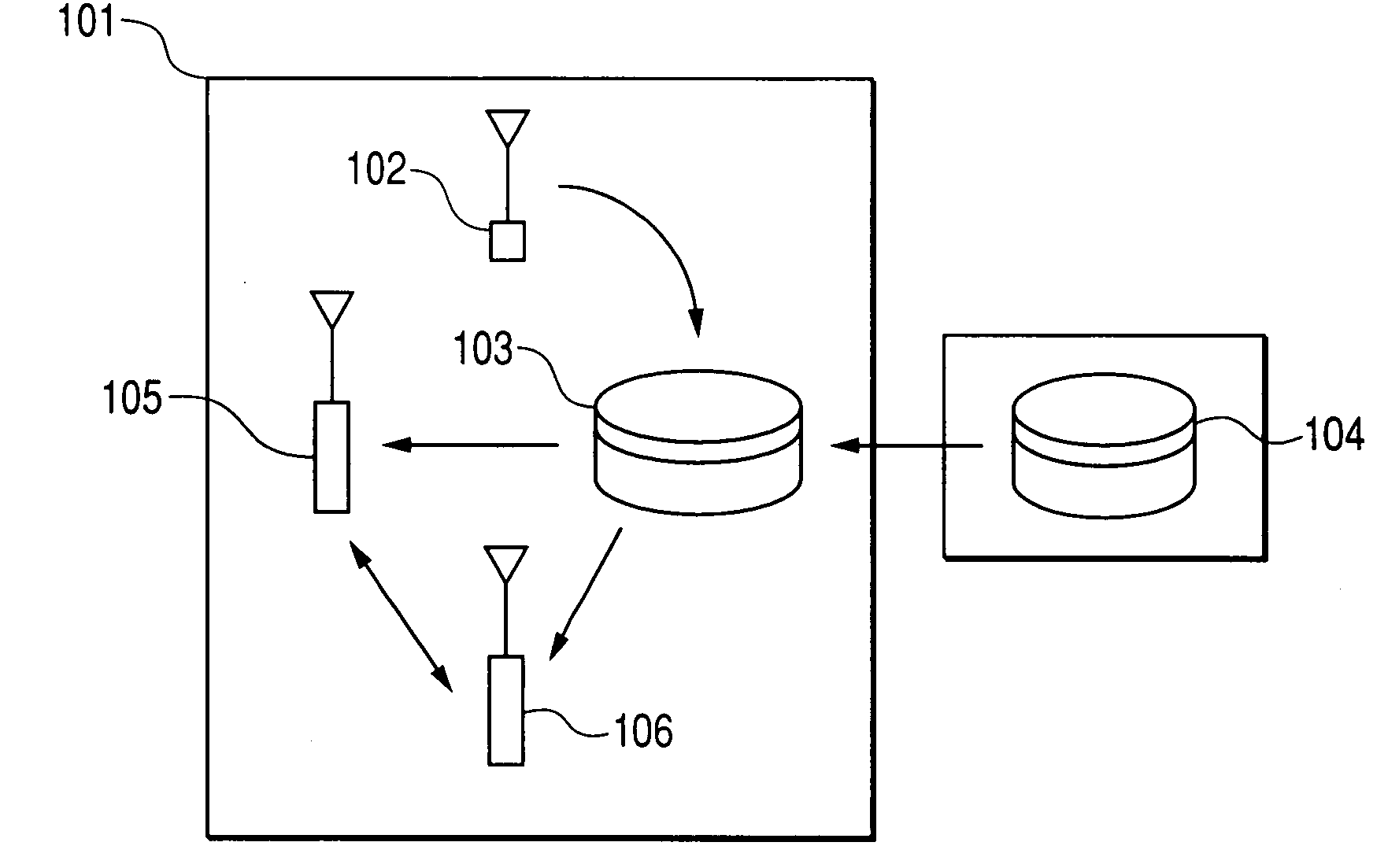
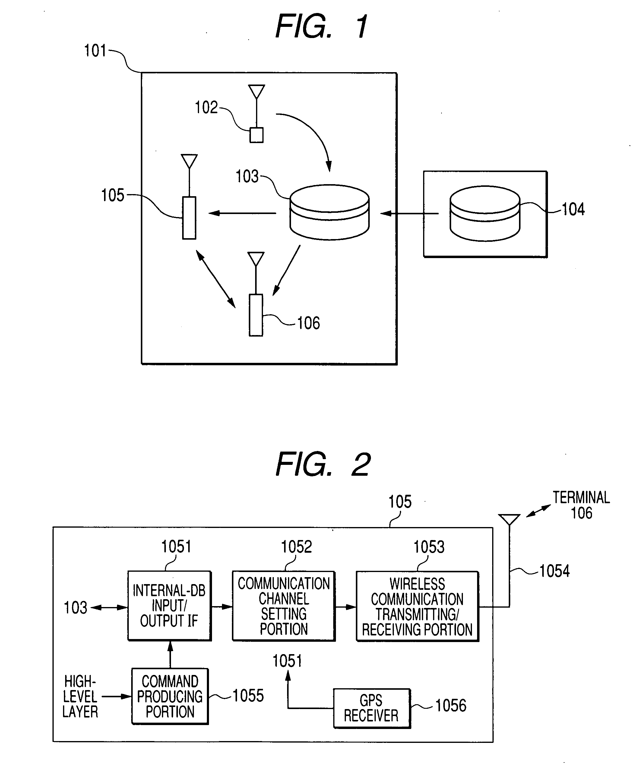
[0050]FIG. 1 is a diagram schematically showing the configuration of a cognitive radio system of a first embodiment of the invention. The cognitive radio system comprises: a wireless communication system 101 including wireless terminal devices 105, 106 that communicate with each other; a wireless-channel use-state detecting device 102 (hereinafter, referred to as “detecting device 102”) which detects the use-state of a wireless channel that can be used by the wireless terminal devices 105, 106; an internal wireless-channel use-state database device 103 (hereinafter, referred to as “internal DB 103”); and an external wireless-channel use-state database device 104 (hereinafter, referred to as “external DB 104”) which stores wireless-channel use-states of frequency bands that are allocated as licensed channels to radio systems different from the wireless communication system 101 (for example, a police radio and an emergency radio which is used in a disaster situation).

[0051]FIG. 2 is ...

second embodiment

[0100] Next, a second-embodiment of the invention will be described. In the first embodiment described above, recognition of an unused channel is performed by the internal DB 103. In the second embodiment, from channel use-state information supplied from the internal DB 103, the terminals 105, 106 recognize an unused channel, and set a communication channel.

[0101]FIG. 9 is a diagram schematically showing the configurations of the terminals 105, 106 in the second embodiment. The terminals 105, 106 have the same configuration, and therefore description of the terminal 106 is omitted. In FIG. 9, components identical with those of FIG. 2 are denoted by the same reference numerals, and their detailed description is omitted. The figure is different from FIG. 2 in that an unused-channel recognizing portion 1056 is disposed.

[0102]FIG. 10 is a sequence diagram showing an example of the process and message exchange in the second embodiment. First, the wireless-channel use-state detecting de...

third embodiment

[0106] Next, a third embodiment of the invention will be described.

[0107]FIG. 11 is a diagram schematically showing the configuration of a system in the third embodiment. In the embodiment, a television broadcast (TV broadcast), and a local area network (W-LAN) using a radio system share a frequency band for the TV broadcast. A TV broadcast antenna 201 transmits a broadcast signal to a certain area by using several frequency bands. At this time, a wireless information DB 202 in a broadcast area stores information such as the frequency band of the current broadcast, the position of a broadcast station, and the radio-wave arrival range.

[0108] In private houses 218, 228, a signal transmitted from the TV broadcast antenna 201 is received by TV receiving antennas 213, 223. The TV receiving antenna 223 is disposed outdoors. It is assumed that TVs 214, 224 can share information by wire or wireless through W-LAN access points (APs) 215, 225 in the private houses 218, 228. Therefore, the T...


PUM


Abstract

A cognitive radio system includes: a state detecting device that scans a frequency band allocated to another radio system than the cognitive radio system to detect a first use-state of the frequency band; a first server including a first gathering unit that receives first information relating to the first use-state and a second gathering unit; a second server that stores a second use-state of the frequency band allocated to the other radio system, the second server configured to provide second information relating to the second use-state to the second gathering unit; and a notifying unit that notifies a terminal device in the cognitive radio system of information of an available channel based on the first information and the second information.

Description

CROSS-REFERENCE TO RELATED APPLICATIONS [0001] This application is based upon and claims the benefit of priority from the prior Japanese Patent Applications No. 2006-126949, filed on Apr. 28, 2006; the entire contents of which are incorporate herein by reference. BACKGROUND [0002] 1. Field [0003] The present invention relates to a cognitive radio system which uses a frequency band licensed to a particular system such as a broadcasting system, only at a time and place which are not used by the system. [0004] 2. Related Art [0005] In order to cope with tightness of frequency resources, a study for a system called “cognitive radio” as a next-generation mobile communication system has been started. The basic concept of cognitive radio technology is that ausable frequency band is scanned to detect a use-state of a wireless channel (frequency), and a usable frequency band is borrowed. Of course, in a radio system in which cognitive radio is used (hereafter, such a system is referred to as...

Claims


Application Information

Patent Timeline
Patent Type & Authority Applications(United States)
IPC IPC(8): H04Q7/24H04W24/00H04W68/00H04W72/04H04W88/14
CPCH04W16/14H04W88/14H04W48/08H04W24/00
Inventor HORIGUCHI, TOMOYAYOSHIDA, HIROSHITOMIOKA, TAZUKONONIN, KATSUYASAKATA, REN
Owner KK TOSHIBA
Why Eureka
Try Eureka