Stable and passive decay heat removal system for liquid metal reactor

a liquid metal reactor and heat removal system technology, applied in the direction of nuclear reactors, nuclear elements, greenhouse gas reduction, etc., can solve the problems of inability to fully function, take several hours for the decay heat removal system to become fully functional, etc., to achieve the effect of effectively removing the decay hea

Inactive Publication Date: 2007-11-01
KOREA ATOMIC ENERGY RES INST
View PDF14 Cites 30 Cited by
  • Summary
  • Abstract
  • Description
  • Claims
  • Application Information

AI Technical Summary

Benefits of technology

[0019] Therefore, the present invention has been made in view of the above problems, and it is an object of the present invention to provide a decay heat removal system which can passively and effectively remove the decay heat immediately after the initiation of an accident without relying on any external support such as an operator action or power supply. To achieve the object, the system is designed so that the natural circulation flow head can be properly built and maintained during an accident from the moment immediately after an accident.

Problems solved by technology

It means that an active decay heat removal system has weak safety features of requiring the operation of active devices such as a motor and valve 15 and also the supply of electric power from the outside for the operation of the valve 15.
In an accident, the normal heat transfer path of the core-IHX-steam generation system is not credited and the sodium in the reactor is heated since the normal heat transfer path is no more available, and the sodium expands.
However, it takes several hours for the sodium to overflow, that is, it takes several hours for the decay heat removal system to become fully functional and be able to remove the decay heat properly.
During this period of time before the system becomes functional, proper heat removal from the reactor pool is not made and it is difficult for the natural circulation flow head to be built up.
Consequently, the core cooling capability becomes low and the temperature of the nuclear fuel in the core can rise excessively high.
Summarizing the description, in a conventional passive decay heat removal system, the volume of the fluid in the reactor needs to be expanded substantially for the system to be able to remove decay heat properly, and the expansion of the fluid volume requires time and a rise of the pool temperature, and this feature results in weak safety features that the core cooling capability is not certain during, the time period of the volume expansion and the temperature in the reactor may become unnecessarily high.

Method used


Image

  • Stable and passive decay heat removal system for liquid metal reactor
  • Stable and passive decay heat removal system for liquid metal reactor
  • Stable and passive decay heat removal system for liquid metal reactor

Examples


first embodiment

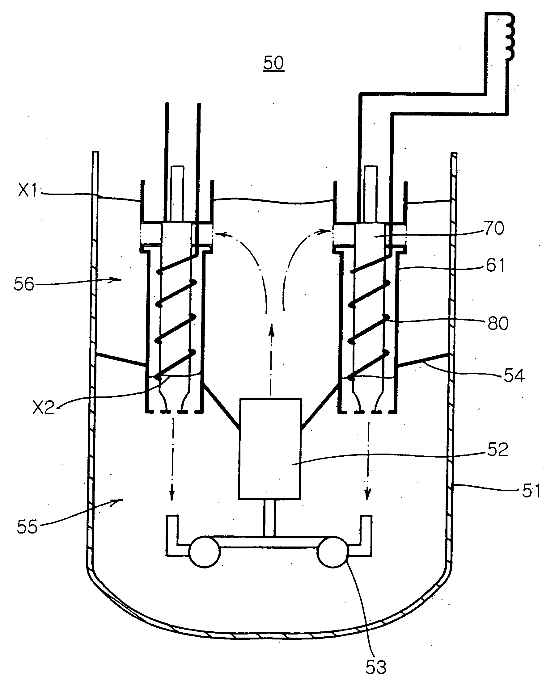
[0037] Structure of decay heat removal system FIG. 3 is a longitudinal-sectional view of a decay heat removal system for a pool type reactor in accordance with the present invention, FIG. 4 is a perspective view illustrating the installation of an intermediate heat exchanger (IHX), a decay heat exchanger (DHX) and a cylinder, FIG. 5 is a cross-sectional view taken along the line A-A of FIG. 4, and FIG. 6 is a cross-sectional view taken along the line B-B of FIG. 4.

[0038] A pool type reactor 50 has intermediate heat exchangers (IHXs) 70 and pumps 53 installed in a reactor vessel 51, which is filled with coolant. As shown in FIG. 3, a hot pool 56 is formed in the reactor vessel 51 of the pool type reactor 50 to contain a hot fluid discharged from a reactor core 52. Further, a cold pool 55 is divided from the hot pool 55 by a partition 54 to contain cooled fluid formed from the hot fluid in the hot pool 55 by heat transfer.

[0039] When the heat generated by nuclear fission in the react...

second embodiment

[0072]FIG. 8 is a perspective view of a decay heat removal system for a pool type reactor in accordance with the present invention, FIG. 9 is a cross-sectional view of the switch valve of FIG. 8 during normal operation, and FIG. 10 is a cross-sectional view of the switch valve of FIG. 8 in an accident.

[0073] The decay heat removal system of the second embodiment of the present invention comprises a switch valve for allowing the fluid in the hot pool to circulate directly into the cylinder.

[0074] The reactor vessel, the IHX 70, the DHX 80 and the pump of the decay heat removal system in this embodiment have the same structures as those in the first embodiment. The components in this embodiment shown in FIG. 8, which are substantially the same as those in the first embodiment, are denoted by the same reference numerals even though they are depicted in different drawings.

[0075] A switch valve 91 is installed on the outer wall of the guide pipe 64 in the cylinder 61. A through hole 94...


PUM


Abstract

A decay heat removal system for a liquid metal reactor, in which a decay heat exchanger (DHX) is installed concentrically with an intermediate heat-exchanger (IHX) in the same cylinder which separates the DHX and IHX from the reactor pool fluid, and serves to remove the reactor core decay heat. The cylinder surrounds the IHX and the DHX, and has an opened top portion protruded out of the level of the fluid in a hot pool, a bottom portion connected to a cold pool and a guide pipe for allowing the passage of the fluid from the hot pool into the IHX. The decay heat removal system can remove decay heat immediately after occurrence of an accident, thereby improves the safety of a nuclear plant.

Description

BACKGROUND OF THE INVENTION [0001] 1. Field of the Invention [0002] The present invention relates to a decay heat removal system of a liquid metal reactor, and introduces a new heat exchange system which integrates a decay heat removal heat exchanger or decay heat exchanger (DHX) and an intermediate heat exchanger (IHX). The new heat exchange system makes it possible for effective decay heat removal to start immediately after an occurrence of an accident while maintaining the complete passivity of the decay heat removal operation. By this invention, passive, proper and stable cooling of the nuclear core can be achieved from the initial stage of an accident. [0003] 2. Description of the Related Art [0004] Liquid Metal Reactor [0005] A liquid metal reactor (LMR) generates heat using fast neutrons from nuclear fission, and simultaneously converts a non-fissile material U238 into a fissile material Pu239, thereby serving as a breeding reactor by producing more fissile material than the ...

Claims


Application Information

Patent Timeline
Patent Type & Authority Applications(United States)
IPC IPC(8): G21C9/00G21C1/02G21C15/02G21C15/18
CPCG21C15/18G21Y2002/201Y02E30/35G21Y2002/50G21Y2004/30G21Y2002/202Y02E30/30
Inventor SIM, YOON SUBKIM, SEONG O.JEON, WON DAE
Owner KOREA ATOMIC ENERGY RES INST
Why Eureka
Try Eureka