
Equalizer bank with interference reduction

a technology of equalizer bank and interference reduction, which is applied in the direction of waveguide type devices, line-transmission details, baseband system details, etc., can solve the problem of inability to adjust by users, and achieve the effect of reducing cost and facilitating equalization of audio signals

Inactive Publication Date: 2007-11-01
HIMAX TECH LTD
View PDF10 Cites 82 Cited by
  • Summary
  • Abstract
  • Description
  • Claims
  • Application Information

AI Technical Summary

Benefits of technology

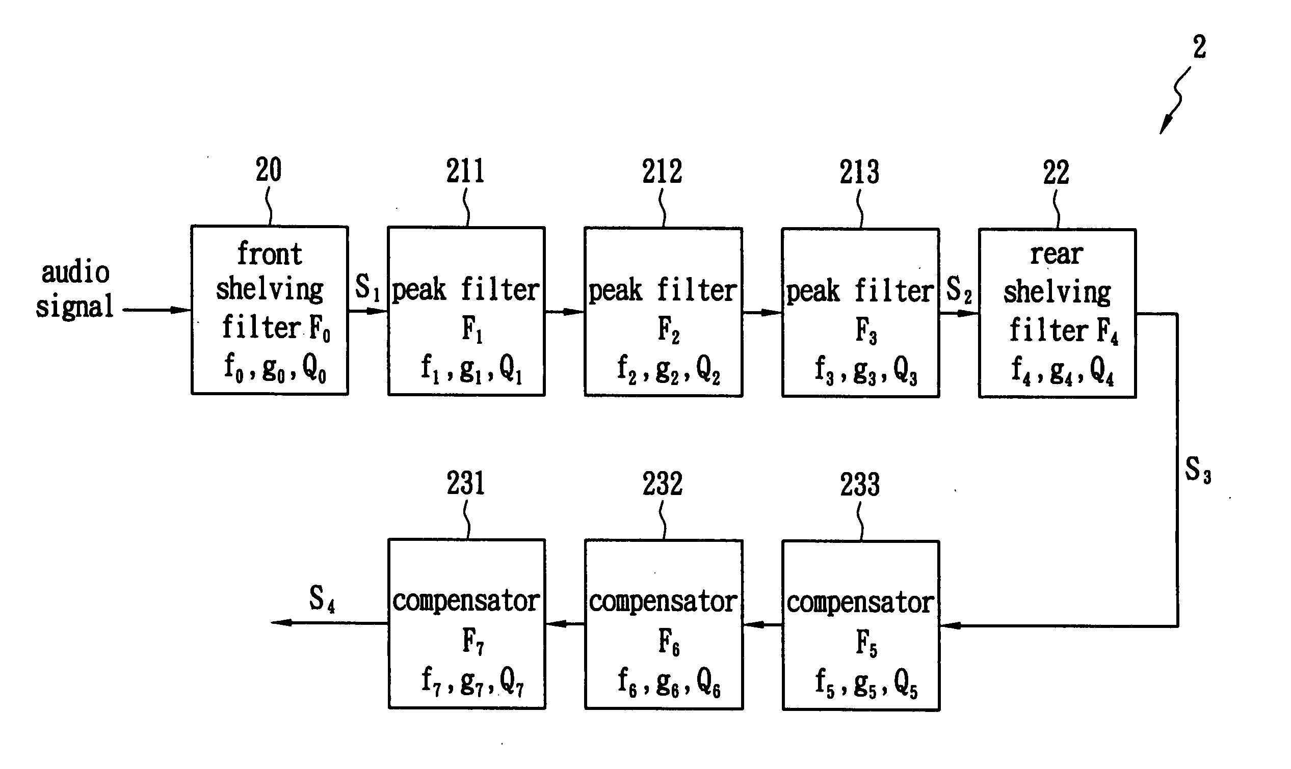
[0008] One objective of the present invention is to provide an equalizer bank with interference reduction, by adding at least one compensator and adjusting the gain thereof to reduce the interference caused between filters.
[0009] Another objective of the present invention is to provide an equalizer bank with interference reduction, which provides a user with convenient operation to equalize the sound.
[0011] Accordingly, when a user selects a specific gain level for the peak filter, the parameters that determine the peak filter and the corresponding compensator are retrieved directly and a complex calculation is skipped. Therefore, an audio signal can be equalized more efficiently with lower cost.

Problems solved by technology

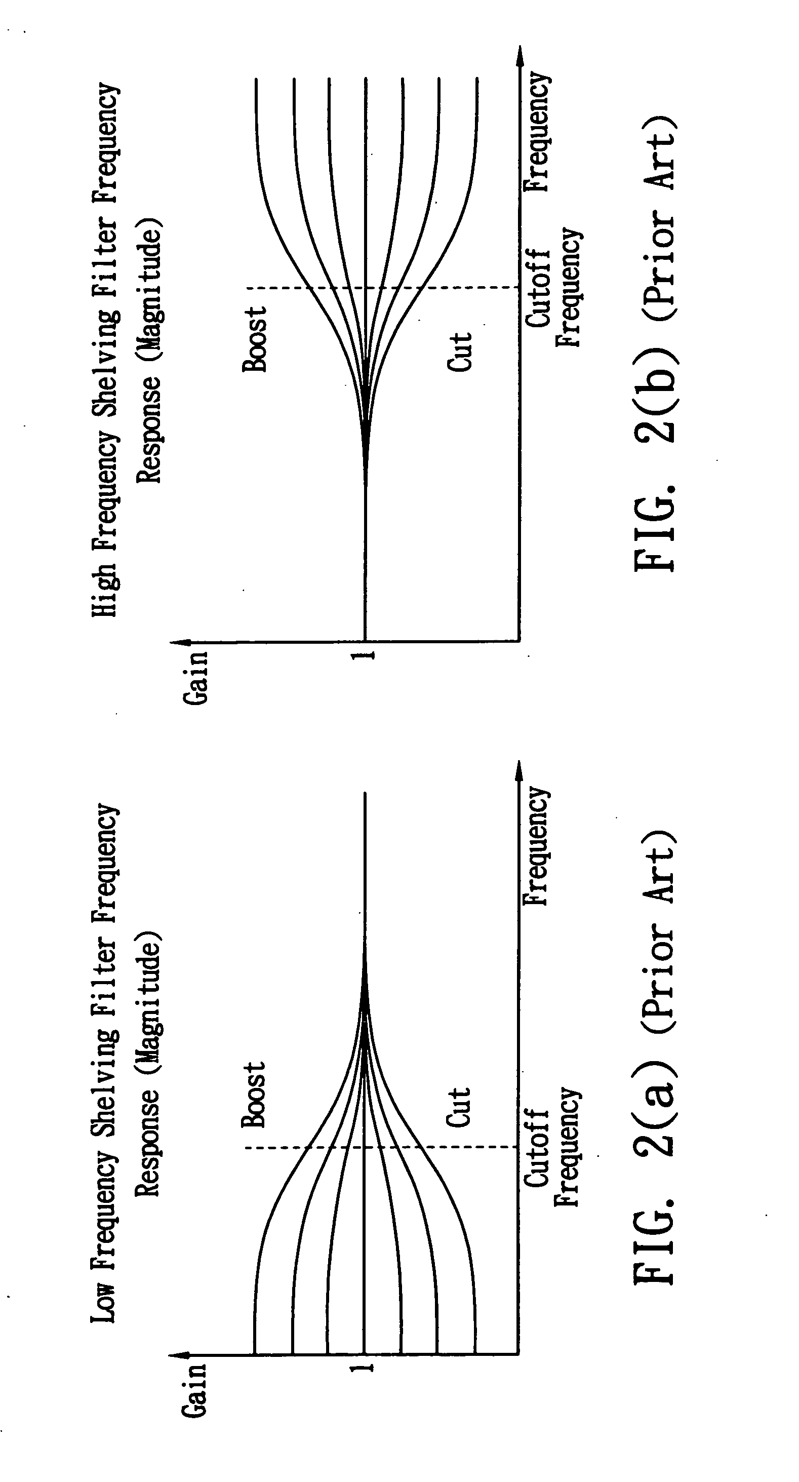
A tone control could be designed that lets the user change this cutoff frequency in addition to the level of cut or boost, but this is usually fixed at the design stage and cannot be adjusted by the user.
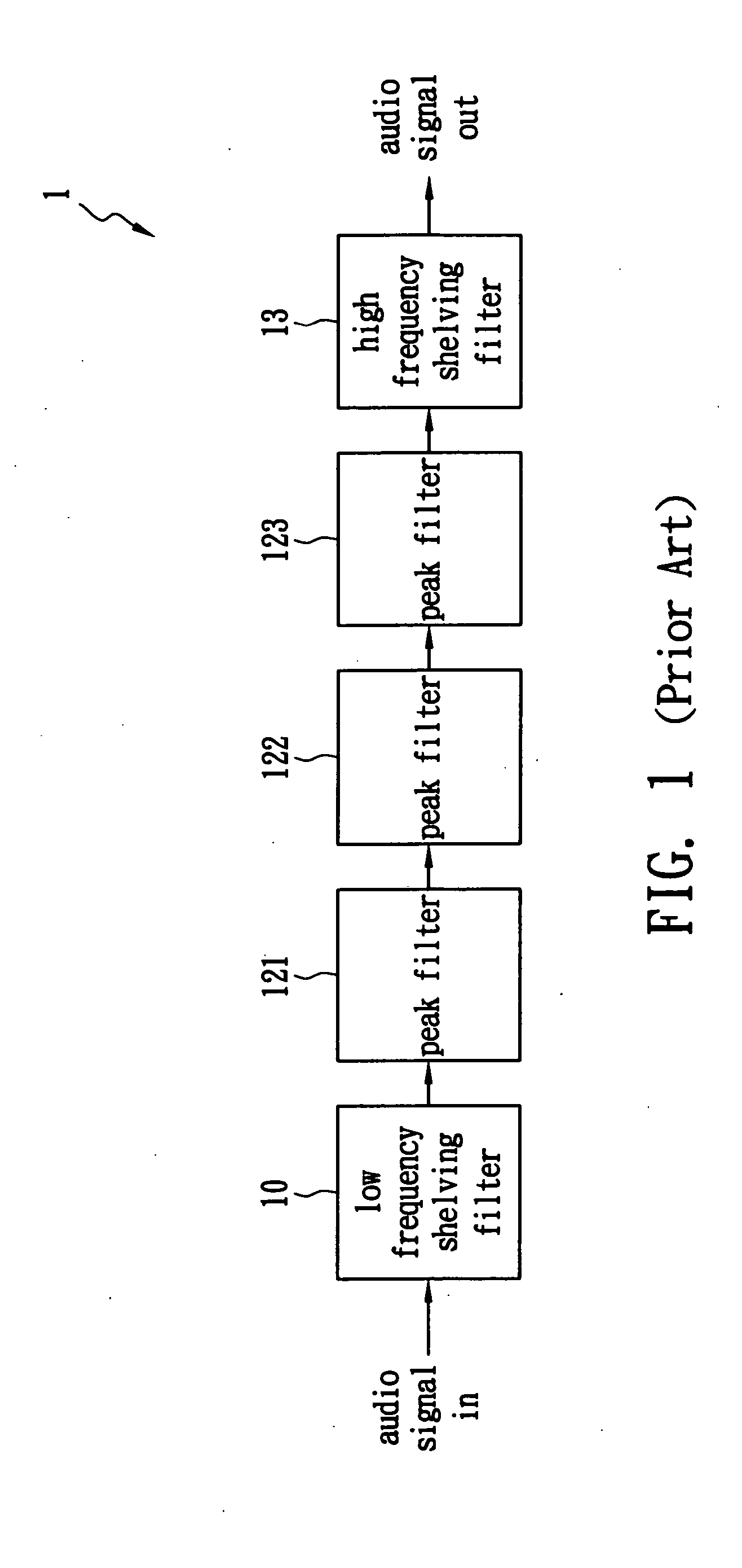
The above two problems result from the interference between filters of FIG. 1.

Method used


Image

  • Equalizer bank with interference reduction
  • Equalizer bank with interference reduction
  • Equalizer bank with interference reduction

Examples


Embodiment Construction

[0020]FIG. 4 shows a block diagram of one embodiment of the equalizer bank 2 of the present invention, which comprises a front-shelving filter 20 characterized by a cutoff frequency f0, a gain g0 and a quality factor Q0, three peak filters 211-213 characterized by center frequencies f1, f2 and f3, gains g1, g2 and g3, and quality factors Q1, Q2 and Q3, a rear-shelving filter 22 characterized by a cutoff frequency f4, a gain g4 and a quality factor Q4, and three compensators 231-233 characterized by center frequencies f5, f6 and f7, gains g5, g6 and g7, and quality factors Q5, Q6 and Q7. An audio signal is fed to the front-shelving filter 10 and transformed into a first signal S1. Then the three peak filters 211-213 transform the first signal S1 into a second signal S2. The rear-shelving filter 22 transforms the second signal S2 into a third signal S3 that exhibits excessive gain accumulation or excessive gain diminution. Afterwards, the three compensators 231-233 compensate for the ...


PUM


Abstract

An equalizer bank with interference reduction is disclosed. The equalizer bank with interference reduction comprises a front-shelving filter, a plurality of peak filters, a rear-shelving filter and a plurality of compensators. The center frequency and the quality factor of each compensator are designed intentionally to be identical to those of the corresponding peak filter. When a user selects a specific gain level, the corresponding parameters that determine the peak filter and the compensator are retrieved directly and a complex calculation is skipped. Therefore, an audio signal can be equalized more efficiently with lower hardware cost.

Description

BACKGROUND OF THE INVENTION [0001] 1. Field of the Invention [0002] The present invention relates to an equalizer bank with interference reduction, and more particularly, to an equalizer bank with interference reduction using plural compensators and equipped with look-up tables. [0003] 2. Description of the Related Art [0004] In digital audio processing, equalizers are required to attain spectral sound equalization. An equalizer bank comprises several equalization filters connected in series or in parallel, so that the equalization filters are adjusted to boost or reduce the value of the specific frequency bands. The most common equalization system is probably the tone controls that can be found on most stereo systems. They provide a quick and easy way to adjust the sound to suit a user's tastes and partially compensate for the furniture configuration in a room. The user will often find the knob controls labeled “bass” and “treble.” Each of those knob controls is associated with a s...

Claims


Application Information

Patent Timeline
Patent Type & Authority Applications(United States)
IPC IPC(8): H03G5/00H04B3/14H01P9/00
CPCH03G5/025H03G5/005
Inventor YEN, KUO HSINLIN, CHIH FENGLEE, KAI TING
Owner HIMAX TECH LTD
Learn More