
Focal plane shutter for digital cameras

Inactive Publication Date: 2007-11-01
NIDEC COPAL CORPORATION
View PDF6 Cites 11 Cited by
  • Summary
  • Abstract
  • Description
  • Claims
  • Application Information

AI Technical Summary

Benefits of technology

[0013]An object of the present invention is to provide a focal plane shutter for digital cameras which is provided with a first blade and a second blade and comprises a first driving member for the first blade in which the driving mechanism of the first blade is connected to the first blade to actuate the first blade toward the starting position of an exposure operation by the biasing force of a set spring and a second driving member for the first blade in which the first blade is actuated through the first driving member for the first blade by the biasing force of a driving spring for the first blade in the exposure operation, so that when a set member is actuated from the initial position, only the second driving member for the first blade is actuated toward the set position against the biasing force of the driving spring for the first blade, but in the first driving member for the first blade, the actuation toward the starting position of the exposure operation is restrained by a restraining member until the initial stage of the actuation that the release button is pushed and the set member is restored to the initial position, wherein the restraining member is always associated with the rotation of the set member so that it is rotated at an angle different from the set member, and thereby the restraint of the first driving member for the first blade in a set condition is securely applied, a shock where the first driving member for the first blade abuts on the second driving member for the first blade at the starting position of the exposure operation by releasing the restraint is absorbed, and the exposure operation can be rapidly started.
[0017]The focal plane shutter for digital cameras further comprises an operating part provided in the second driving member for the first blade; an electromagnet for the first blade energized at the initial stage of the release, allowing the exposure operation of the first blade to be performed by the second driving member for the first blade when power to the electromagnet is disconnected after the operation of restoration to the initial position of the set member; an electromagnet for the second blade energized at the initial stage of the release, allowing the exposure operation of the second blade to be performed by the driving member for the second blade when power to the electromagnet is disconnected after the start of the exposure operation of the first blade; and a switch means operated by the operating part on completion of the exposure operation of the first blade, constructed as a signal source for preventing the set member from starting the next set operation when the switch means is not operated at preset time after the electromagnet for the first blade is energized. In the shutter constructed in this way, even when trouble is produced in the control circuit of the electromagnet, no error is caused to an associated structure including the set member, the restraining member, and the first driving member for the first blade in the next set operation. In this case, when the switch means is also constructed as a signal source for error display, it becomes possible to readily recognize the error.
[0018]In the present invention, the focal plane shutter for digital cameras is provided with the first blade and the second blade so that the driving mechanism of the first blade includes the first driving member for the first blade connected to the first blade and the second driving member for the first blade actuating the first blade through the first driving member for the first blade by the biasing force of the driving spring for the first blade in the exposure operation, and so that the first driving member for the first blade is restrained by the restraining member from following up the second driving member for the first blade at the initial stage of the set operation of the set member, and the front of the image sensor is opened and an image of an object can be observed through a liquid crystal display device in the set condition. In this case, the restraining member and the set member are mounted to different shanks so that the restraining member is always rotated in association with the rotation of the set member, but are different in the angle of rotation. Consequently, in the set condition of the set member, the actuation of the first driving member for the first blade caused by the set spring can be securely restrained in the proximity of the position where the exposure operation is completed, and when the set member is restored to the initial position after the release of the camera, the first driving member for the first blade is actuated by following up the restraining member and its restraint is released immediately before the set member reaches the initial position. Thus, unlike the conventional structure that the restraint is released in the proximity of the position where the exposure operation is completed, it is not necessary to effect stabilization in the release, and after the restraint is released, a shock of an abutment on the second driving member for the first blade at the starting position of the exposure operation is slight and the exposure operation can be rapidly started.

Problems solved by technology

Hence, after the set member is restored to the initial position, the exposure operation of the first blade cannot be immediately started and after the release button is pushed, time required until the first blade starts the exposure operation becomes long.
This causes the problem that when the object is moving, there is a high possibility of missing a shutter chance.
However, it is extremely difficult to actually mass-produce the focal plane shutter constructed in this way.
Consequently, in the case where such focal plane shutters are mass-produced, even though the restraining member can be rotated by the engagement of the engaging part with the parts to be engaged, sometimes the hook section is not favorably flexed and the engagement of the engaging part with the parts to be engaged is not smoothly released when the rotation of the restraining member is stopped.
Moreover, cases sometimes occur in which, while the set member is repeatedly rotated, the hook section, after being flexed, ceases to be restored to a preset original, the engagement of the engaging part with the parts to be engaged is not favorably carried out, and the restraining member cannot be securely rotated by the set member.

Method used


Image

  • Focal plane shutter for digital cameras
  • Focal plane shutter for digital cameras
  • Focal plane shutter for digital cameras

Examples


embodiment 1

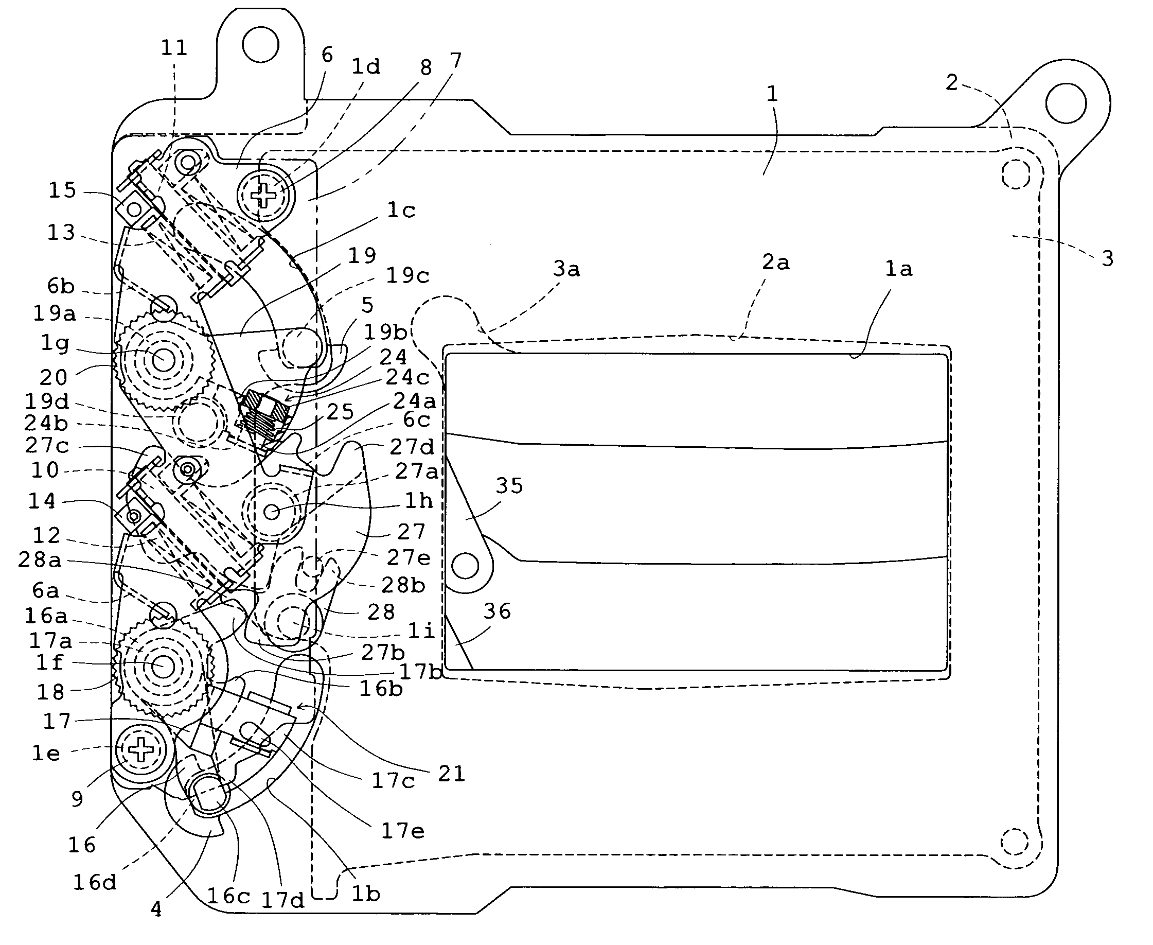
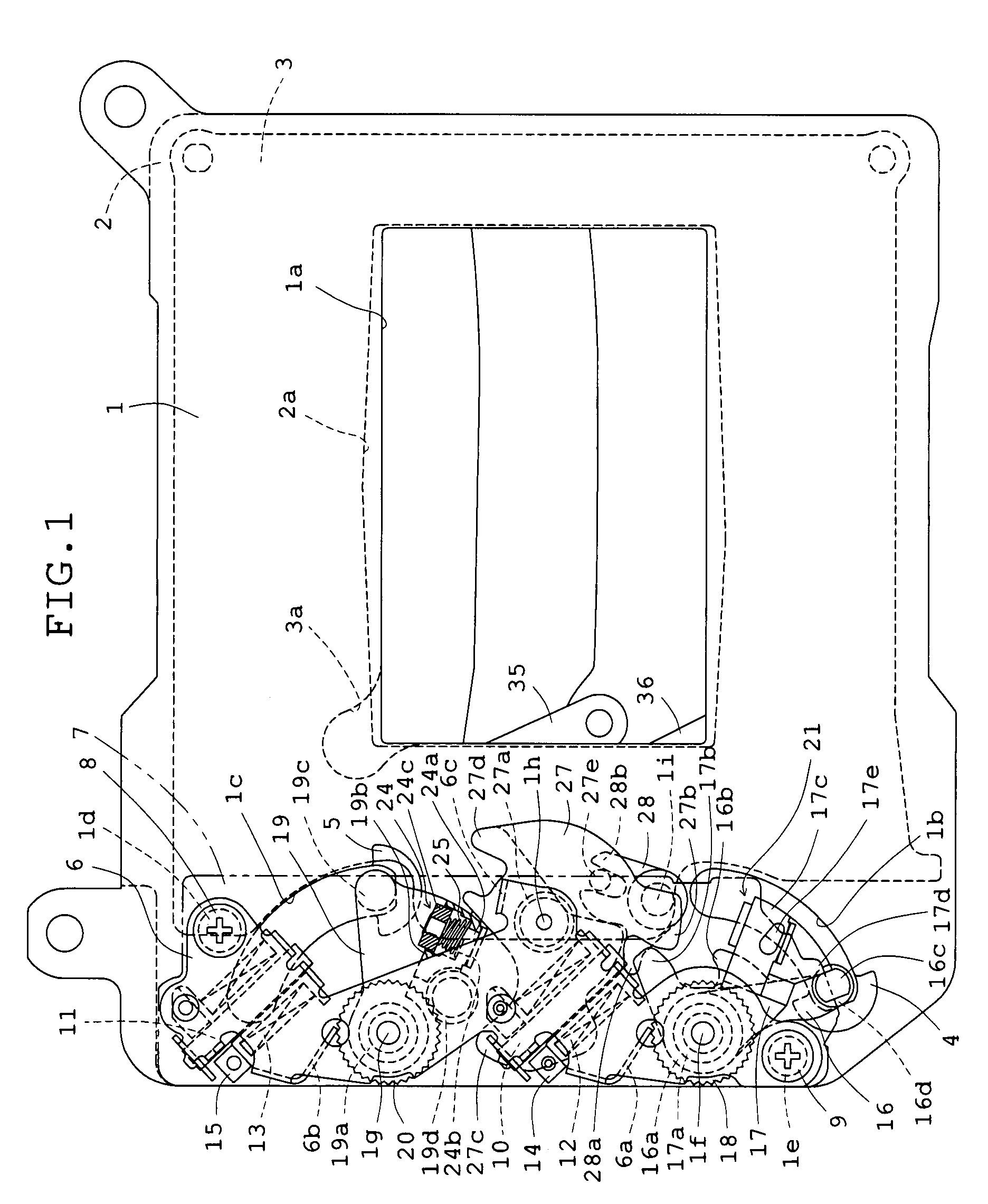
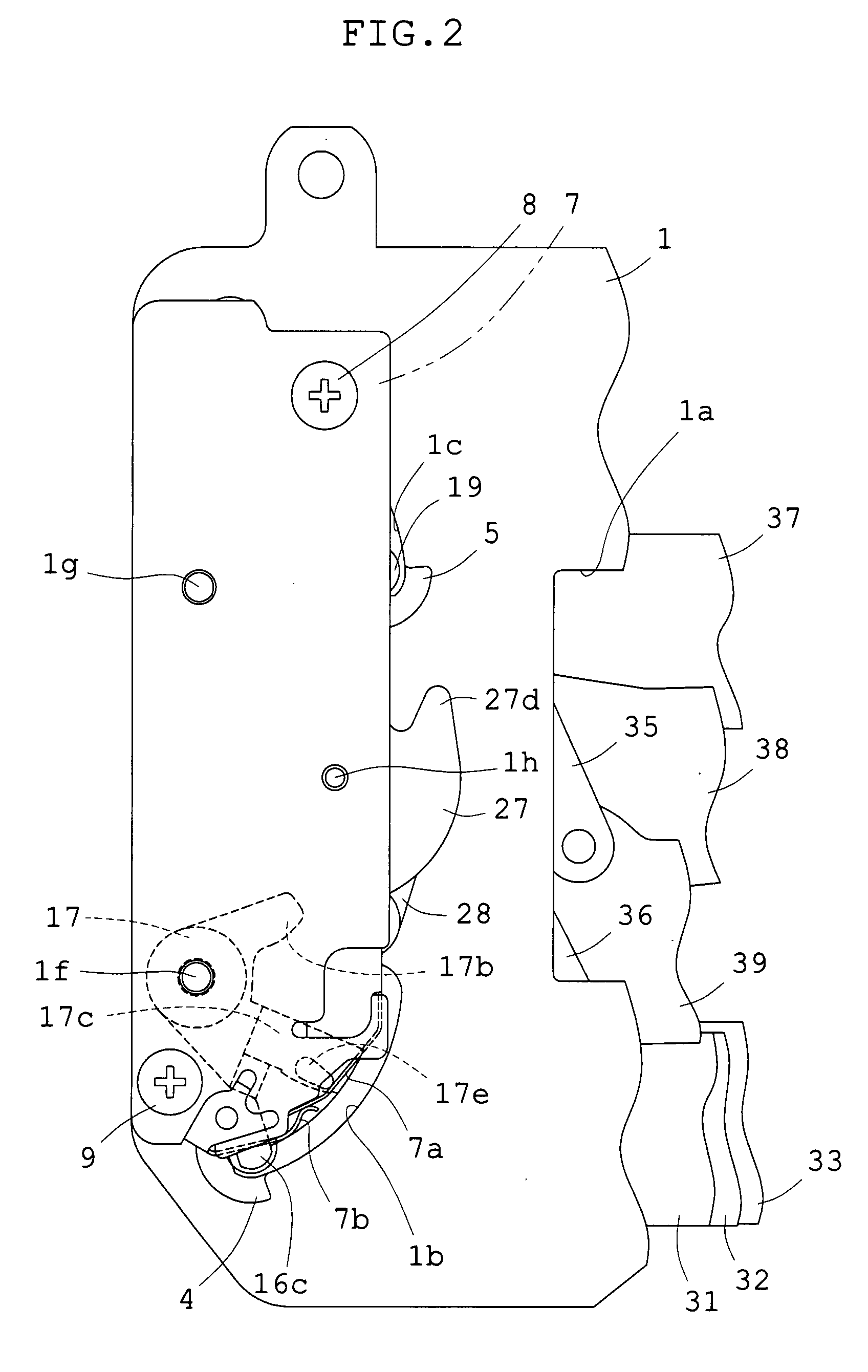
[0035]FIG. 1 is a plan view showing Embodiment 1 of the focal plane shutter for digital cameras of the present invention incorporated in a camera, viewed from the object side, in which the contour of a printed wiring board is indicated by a two-dotted chain line to facilitate a comprehension of a state immediate after the exposure operation of components is completed, and FIG. 2 is a plan view showing the printed wiring board and a switch mechanism attached thereto by enlarging a part of FIG. 1. FIG. 3 is a plan view showing Embodiment 1, like FIG. 1, by enlarging a part of FIG. 1. FIG. 4 is a sectional view showing the shutter viewed from the right side of FIGS. 2 and 3 to facilitate the comprehension of the overlapping relation of components. FIGS. 5-11 are plan views showing only main components necessary for the explanation of actuation, of components of FIG. 3. FIG. 5 shows a state immediately after the completion of the exposure operation as in FIG. 3. FIG. 6 shows a state of ...

embodiment 2

[0074]Subsequently, Embodiment 2 will be explained. FIG. 13, like FIG. 3, is a plan view showing a state immediate after the completion of the exposure operation, and the second driving member 17 for the first blade is shown without cutting the mounting portion 17c. FIG. 14 is a sectional view showing the shutter viewed from the right side of FIG. 13 to facilitate the comprehension of the overlapping relation of components. The structure of FIG. 2 used for the explanation of Embodiment 1 is also used for the explanation of Embodiment 2, except for the restraining member 28. FIG. 12 used for the description of the operation of the Embodiment 1 is also used for that of Embodiment 2. In Embodiment 2, most of components are identical with the components of Embodiment 1. In FIGS. 13 and 14, like numerals are used for like members and parts with respect to Embodiment 1. Thus, in a structural description described below, reference is chiefly made to structures different from Embodiment 1.

[...


PUM


Abstract

A focal plane shutter for digital cameras includes a first driving member for a first blade and a second driving member for the first blade, mounted to the same shank; arms for the first blade on which a set spring is hooked; and a set member for restraining the first driving member for the first blade in the proximity of the position where the exposure operation is completed, at a set position by rotating a restraining member, and actuating the first driving member for the first blade to the starting position of the exposure operation in the restoration to the initial position immediately after the release.

Description

BACKGROUND OF THE INVENTION[0001]1. Field of the Invention[0002]This invention relates to a focal plane shutter for digital cameras.[0003]2. Description of Related Art[0004]Of focal plane shutters for digital cameras, like focal plane shutters for silver-halide film cameras, there are types that two shutters, a first blade and a second blade, are provided and the first blade and the second blade are actuated successively in the same direction in photography so that the imaging surface of an image sensor, such as a CCD, is continuously exposed from one end to the other. These first and second blades are connected to a driving member for the first blade and a driving member for the second blade, and after the release of a camera, power to an electromagnet for the first blade and an electromagnet for the second blade is disconnected in turn so that the above driving members are rotated successively by biasing forces of their driving springs and thereby an exposure operation is performe...

Claims


Application Information

Patent Timeline
IPC IPC(8): G03B9/40
CPCG03B9/40
Inventor YOSHIDA, KATSUNOBUINOUE, NOBUYOSHI
Owner NIDEC COPAL CORPORATION
Features
  • Generate Ideas
  • Intellectual Property
  • Life Sciences
  • Materials
  • Tech Scout
  • Unparalleled Data Quality
  • Higher Quality Content
  • 60% Fewer Hallucinations
Learn More