
Safety valve for gastight battery and gastight battery using safety valve

Active Publication Date: 2011-09-29
SHENZHEN KEDALI IND CO LTD
View PDF12 Cites 6 Cited by
  • Summary
  • Abstract
  • Description
  • Claims
  • Application Information

AI Technical Summary

Benefits of technology

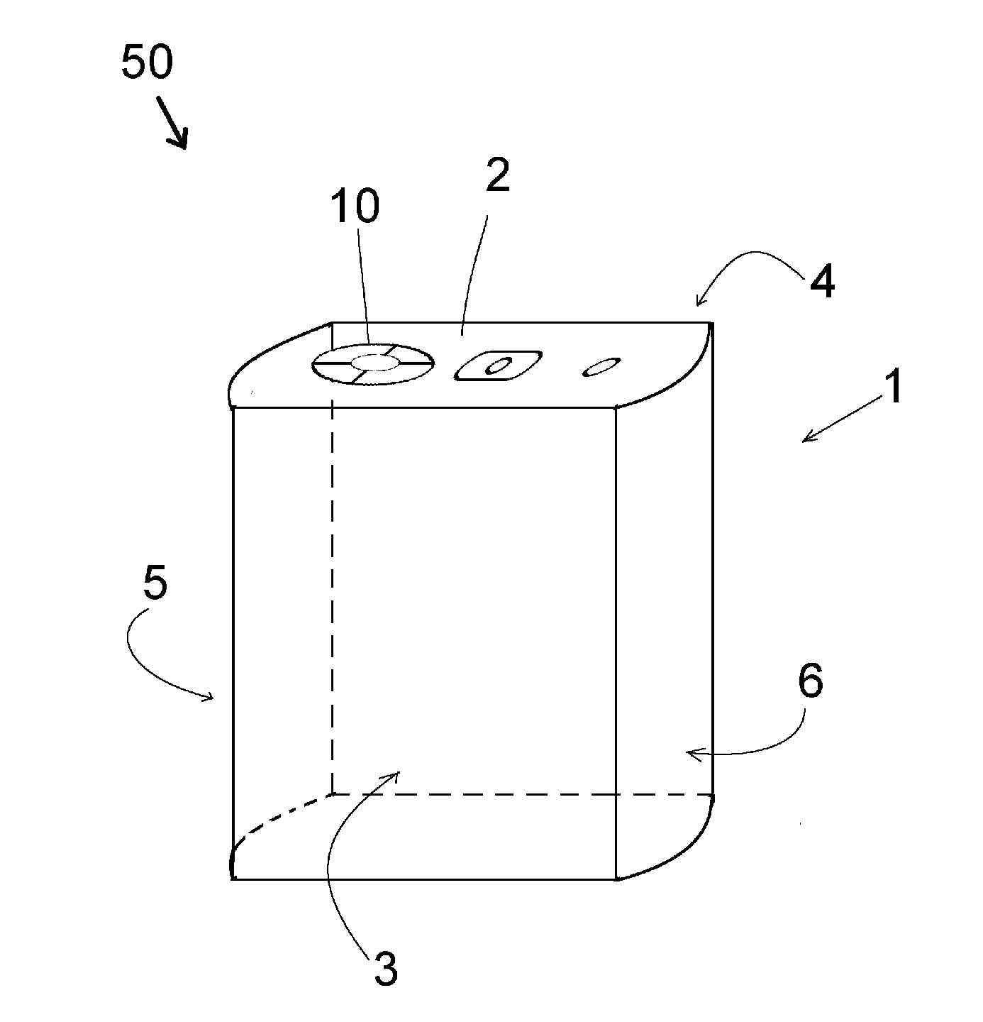
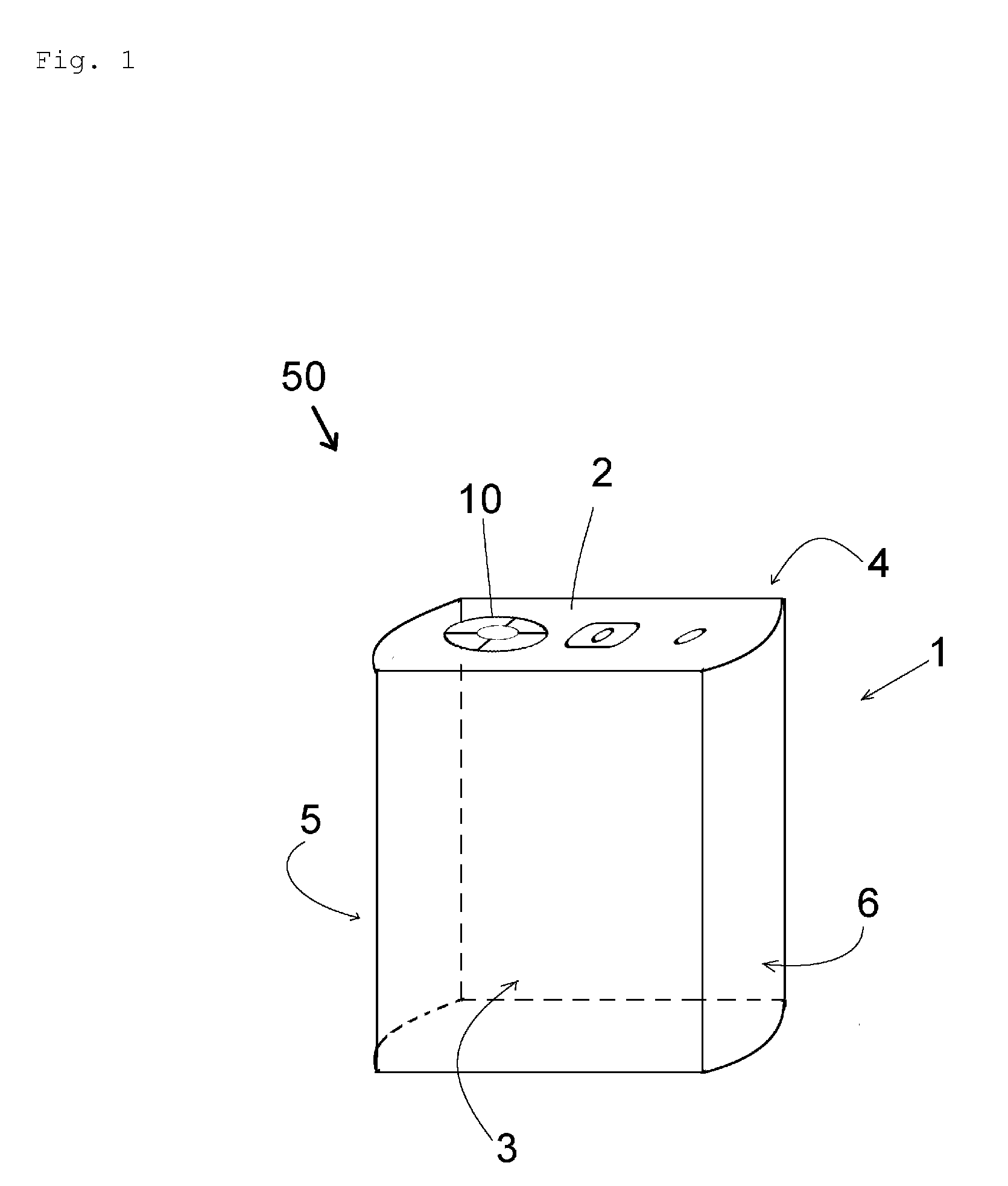
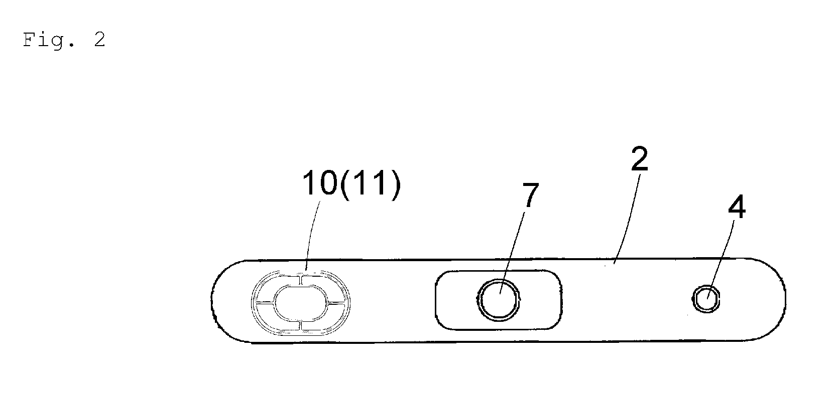
[0059]In this manner, by forming the inner annular groove 13 in the area inside the outer annular groove 12 of the safety valve 10 and by forming the lateral-directional connecting grooves 15 and the longitudinal-directional connecting grooves 16 which connect the inner annular groove 13 and the outer annular groove 12 to each other, when a battery internal pressure is applied to the safety valve 10, the safety valve 10 receives a force which intends to deform the safety valve 10 mounted on the battery case 1 into a dome-like shape so that a large stress is applied to the inner annular groove 13 first.
[0060]Since respective one ends of the connecting grooves 15, 16 are connected to the inner annular groove 13, deformation stress is concentrated on the intersections between the inner annular groove 13 and the connecting grooves 15, 16.
[0061]As a result, when the battery internal pressure is elevated, the stress is propagated to the outer annular groove 12 with the intersections between the inner annular groove 13 and the connecting grooves 15, 16 as breaking starting points and hence, the outer annular groove 12 formed of a thinnest wall is broken whereby the safety valve is operated rapidly.Example
[0062]Safety valves are manufactured using an aluminum alloy plate, and the safety valves are fixed to battery cases by laser welding thus forming dummy batteries of examples.
[0063]As the dummy batteries of the examples, two kinds of dummy batteries are prepared, wherein a thickness (remaining wall thickness) of an outer annular groove of one safety valve is set to 30 μm (

Problems solved by technology

However, recently, along with the increase of battery capacity, an amount of gas which is generated in an abnormal state such as an overcharge is increased compared to the past.
When a gas which is generated in an abnormal state is not released at a stretch from a opened hole of a safety valve, there is a possibility of explosion of a battery case.
The above-mentioned safety valves of the prior art cannot cope with such a drawback.

Method used


Image

  • Safety valve for gastight battery and gastight battery using safety valve
  • Safety valve for gastight battery and gastight battery using safety valve
  • Safety valve for gastight battery and gastight battery using safety valve

Examples


example

[0062]Safety valves are manufactured using an aluminum alloy plate, and the safety valves are fixed to battery cases by laser welding thus forming dummy batteries of examples.

[0063]As the dummy batteries of the examples, two kinds of dummy batteries are prepared, wherein a thickness (remaining wall thickness) of an outer annular groove of one safety valve is set to 30 μm (example 1 shown in FIG. 8A), and a thickness (remaining wall thickness) of an outer annular groove of the other safety valve is set to 50 μm (example 2 shown in FIG. 8B). Remaining wall thickness of the inner annular groove is set to 70 μm in the example 1 and 90 μm in the example 2 respectively.

[0064]Further, comparison examples where a rate between a distance Y from the center of the safety valve to the inner annular groove and a radius X of the safety valve is changed from each other are prepared and are subjected to an experiment.

[0065]Here, a distance between the center of the safety valve 10 and a stepped por...


PUM


Abstract

A safety valve for a battery which is mounted on a sealing plate for sealing an opening portion of a gastight battery case, and which can rapidly release a gas in the battery when a battery internal pressure is elevated is provided. In a safety valve for a gastight battery, a thin-wall valve element is formed on a sealing plate which seals an opening portion of a battery case, and the valve element is opened when a battery internal pressure becomes a predetermined value or more so as to release a gas in the battery to the outside of the battery. The safety valve includes: an outer annular groove formed of an annular thin wall which is formed on the periphery of the valve element and is provided for releasing the whole valve element; an inner annular groove formed of an annular thin wall which is arranged in an area inside the outer annular groove; and a connecting groove formed of a straight thin wall which connects the outer annular groove and the inner annular groove to each other. A wall thickness of the inner annular groove and a wall thickness of the connecting groove are set larger than a wall thickness of the outer annular groove.

Description

BACKGROUND OF THE INVENTION[0001]1. Field of the Invention[0002]The present invention relates to a safety valve for a gastight battery and a gastight battery using the safety valve, and more particularly to a safety valve having a valve element function which is communicated with the outside when a pressure in the battery becomes excessively large.[0003]2. Description of the Related Art[0004]With respect to a gastight battery, when an abnormal reaction occurs in the battery for some reasons so that a pressure in the battery is elevated, there exists a possibility that the gastight battery causes damages on a human body or objects due to the explosion of the battery per se. To avoid such a possibility, it is necessary to release a gas in the battery before the explosion occurs. A safety valve is provided to a battery case for this end.[0005]The safety valve has a valve element which is broken and is opened with a predesigned internal pressure so as to release an internal gas to the o...

Claims


Application Information

Patent Timeline
IPC IPC(8): H01M2/12F16K17/02
CPCH01M2/1241H01M2200/20H01M2/34Y10T137/7837Y10T137/1744Y02E60/10H01M50/3425
Inventor IKEDA, AKIRA
Owner SHENZHEN KEDALI IND CO LTD
Learn More