Offshore structure and method for attaching a tube or cable to an appliance of an offshore structure

a technology of offshore structure and tube or cable, which is applied in the direction of cable arrangement between relatively moving parts, cable installation on floats, machines/engines, etc., can solve the problems of tube or cable defects, process is rather time-consuming,

Active Publication Date: 2022-08-16
SIEMENS GAMESA RENEWABLE ENERGY AS
View PDF27 Cites 0 Cited by
  • Summary
  • Abstract
  • Description
  • Claims
  • Application Information

AI Technical Summary

Benefits of technology

[0012]The guiding means can guide the tube or a cable in such a way that the tube or cable enters the platform essentially orthogonally to the platform and / or essentially vertically at the entry point and that the tube or cable extends essentially in parallel to the platform and / or essentially horizontally at the connection point. This allows for a horizontal pulling of the cable or tube and therefore for a reduced height of the highest point that the cable or tube needs to reach during the installation. This is especially advantageous when the platform or at least the area of the platform that comprises the entry point is covered by a roof since only a limited height is available in this case to pull or push in the cable or tube. Guiding the cable such that a horizontal pull in or push in is possible also allows for a pull in or a push in without using a scaffolding or other techniques to pull or push the cable or tube to large heights above the platform.
[0017]The guiding means can guide the tube or cable in such a way that a minimum bending radius of the tube or cable is increased by the guiding means. If the guiding means would not be used and the tube or cable would change its orientation between the entry point and the connection point the bending radius would be determined by the properties of the tube or the cable and the weight of the freely hanging section of the tube or cable. The cable would typically hang free between the entry point and the water surface or the seabed. This could lead to a small bending radius and therefore a large stress or strain on the tube or cable which could lead to defects of the tube or cable. By guiding the tube or cable along a predetermined path the minimum bending radius can be increased.
[0018]The guiding means can guide the tube or cable to a guidance point that has a larger distance to the platform and / or a larger vertical height than the connection point. The entry point can be closer to the platform and / or have a lower vertical height than the connection point. In other words, the guiding path can first climb to a relatively high guiding point and then descend again to the connection point. This shape of guiding path increases the length of wire that can be pulled onto the platform when the space on the platform or between the platform and the roof is limited. It can also serve to increase the minimum bending radius required to guide the tube or cable from the entry point to the connection point.
[0020]The guiding means can comprise multiple rollers or groups of rollers spaced along the guidance path. As previous discussed the guiding means are preferably used during the installation of the tube or the cable, especially while the tube or cable is pushed or pulled along the guidance path. The use of multiple rollers or groups of rollers spaced along the guidance path allows for a clearly defined guiding path wherein the cable or tube can hardly deviate from the given guidance path while keeping the friction between the guiding means and the cable or tube low. It therefore allows for the pushing or pulling of the cable or tube with a relatively low resistance.
[0023]The rollers or groups of rollers can be attached to the platform via at least one rod. The rods can be connected directly to the platform or to walls and / or a roof that are connected to the platform. The use of rods allows for simple means to position the rollers or groups of rollers or a component that carries the rollers or groups of rollers with respect to the platform. The guidance means and especially the rods can be detachably attached to the platform or to further components connected to the platform to allow a removal of the guidance system after installing the tube or cable.
[0034]The inventive method can preferably be performed using the offshore structure according to embodiments of the present invention. The method can also be expanded by the features discussed with respect to the inventive offshore structure and vice versa. The inventive method allows for easy installation of tubes or cables on an offshore structure, especially when the space on a platform or within an enclosure of a part of a platform is limited.

Problems solved by technology

This process is however rather time consuming and can be problematic due to the harsh conditions often encountered on open water.
This could lead to a small bending radius and therefore a large stress or strain on the tube or cable which could lead to defects of the tube or cable.

Method used


Image

  • Offshore structure and method for attaching a tube or cable to an appliance of an offshore structure
  • Offshore structure and method for attaching a tube or cable to an appliance of an offshore structure
  • Offshore structure and method for attaching a tube or cable to an appliance of an offshore structure

Examples


Embodiment Construction

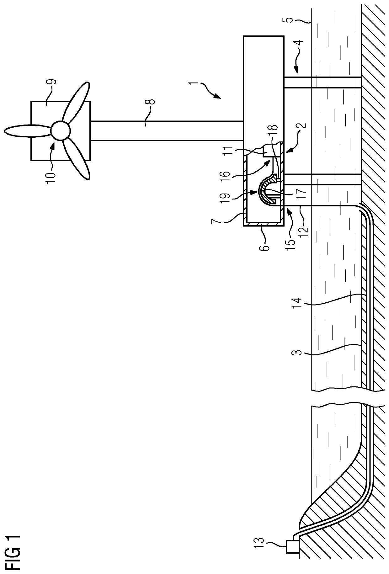
[0048]FIG. 1 shows an offshore structure 1 that is an offshore wind turbine in the present example. The offshore structure 1 comprises a platform 2 that is connected to the seabed 3 via a foundation 4 that carries the platform 2. The surface area of the platform 2 is covered by walls 6 and a roof 7. In the shown example the platform 2 is completely covered by the walls 6 and the roof 7, it would however be possible to cover only parts of the platform 2 or to use a completely open platform 2.

[0049]The platform 2 also carries a tower 8 that in turn carries a nacelle 9 housing a wind turbine 10. The foundation 4 has a sufficient height to keep the platform 2 above the water level 5.

[0050]An appliance 11, e.g. a transformer or switching gear, of the offshore structure 1 is used to condition the power generated by the wind turbine 10. This power should then be transferred to an onshore station 13. Alternatively, it would be possible to first transfer the power to other offshore structure...


PUM


Abstract

Provided is an offshore structure, especially offshore wind turbine, including a platform that is connected to the seabed, especially via a foundation that carries the platform, and an appliance, wherein it comprises guiding means for guiding at least one tube or cable along a guidance path from a respective entry point at which the tube or cable enters the platform to a respective connection point at which the tube or cable is connected or connectable to the appliance.

Description

CROSS-REFERENCE TO RELATED APPLICATIONS[0001]This application claims priority to European Application No. 17201918.4, having a filing date of Nov. 15, 2017 the entire contents of which are hereby incorporated by reference.FIELD OF TECHNOLOGY[0002]The following concerns an offshore structure, especially an offshore wind turbine, comprising a platform that is connected to the seabed, especially via a foundation that carries the platform, and an appliance. Additionally, the following concerns a method for attaching a tube or cable to an appliance of an offshore structure.BACKGROUND[0003]Offshore facilities such as wind turbines mounted on offshore support structures tend to require connections to other offshore structures and / or onshore facilities, e.g. for transferring generated power to an onshore facility. It can also be advantageous to transport fluids or gas from or to an offshore structure. Undersea cables and / or tubes can be used to transport electricity, gas and / or fluids from ...

Claims


Application Information

Patent Timeline
Patent Type & Authority Patents(United States)
IPC IPC(8): F03D80/80E02B17/00F16L1/032H02G1/08H02G9/02H02G9/12H02G1/10H02G11/00F03D9/25F16L1/12
CPCF03D80/85E02B17/00F16L1/032H02G1/088H02G1/10H02G9/02H02G9/12E02B2017/0056E02B2017/0091F03D9/255F05B2240/95F16L1/12H02G1/086H02G11/006
Inventor SOERENSEN, JOHNNY
Owner SIEMENS GAMESA RENEWABLE ENERGY AS
Why Eureka
Try Eureka