Handpiece for the phacoemulsification of an eye lens
a technology of eye lens and phacoemulsification, which is applied in the field of handpiece for the phacoemulsification of eye lens, can solve the problems of cornea in particular being subject to a very large thermal load, tissue region around the needle burning,
- Summary
- Abstract
- Description
- Claims
- Application Information
AI Technical Summary
Benefits of technology
Problems solved by technology
Method used
Image
Examples
first embodiment
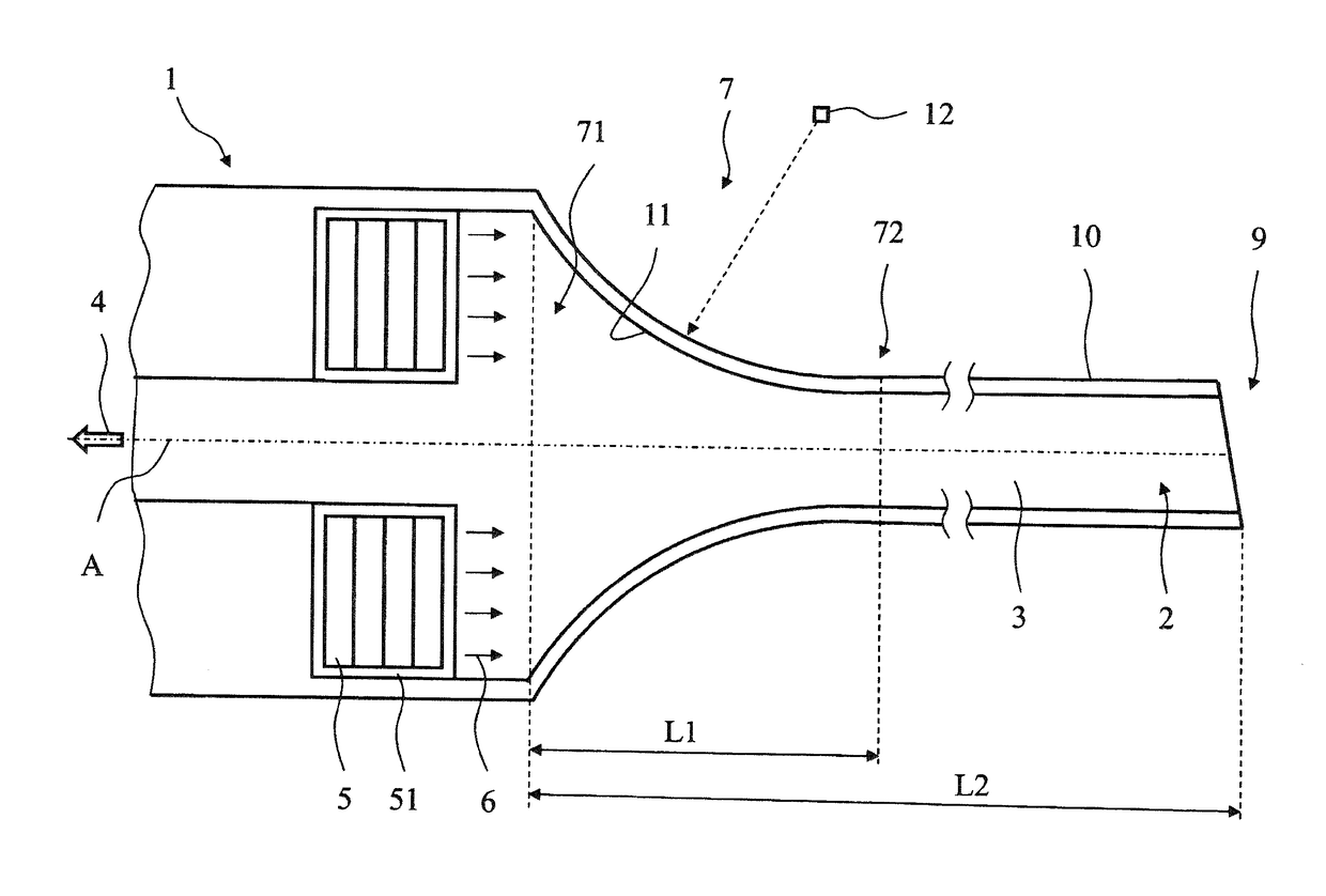
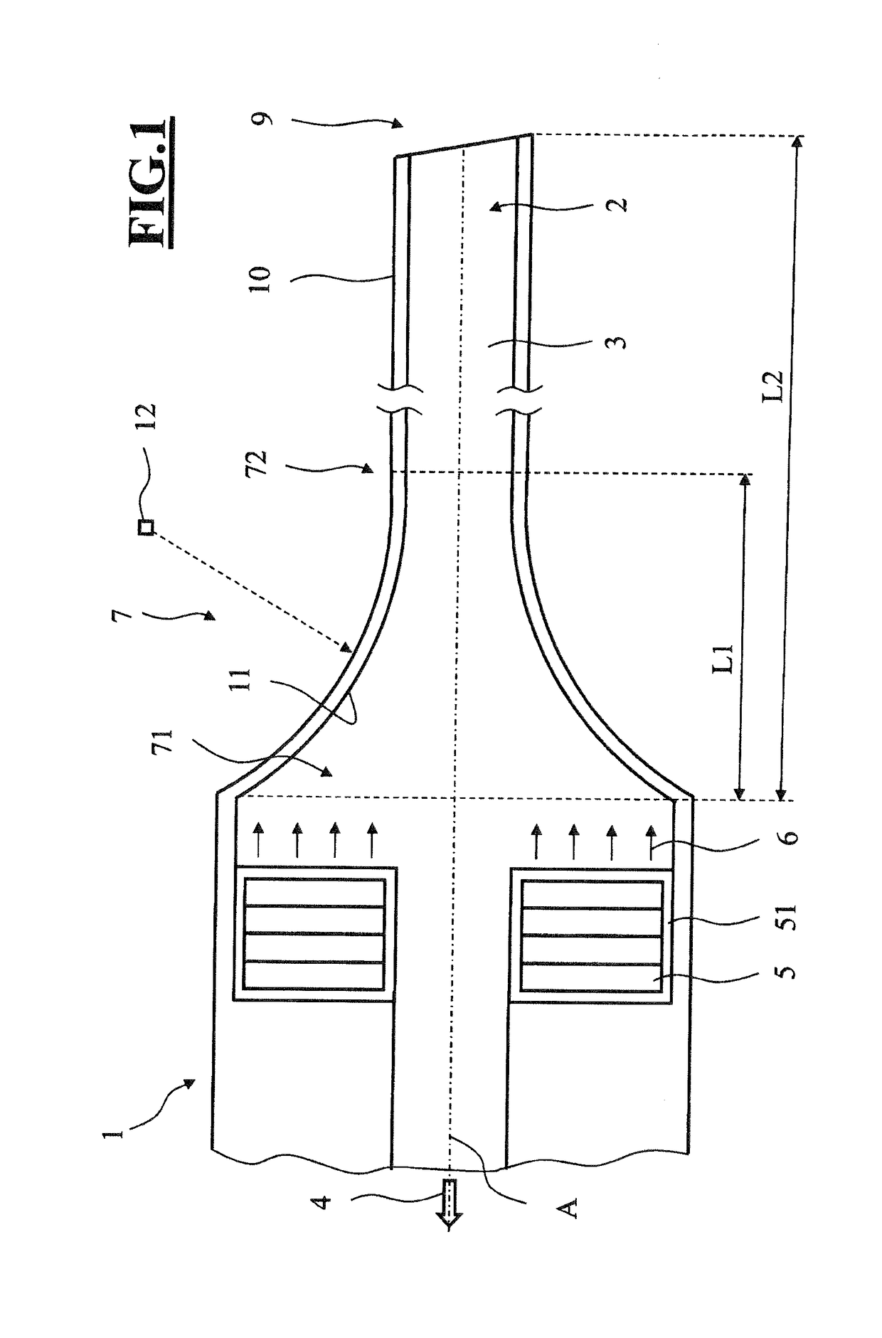
[0029]FIG. 1 shows a handpiece 1 in accordance with the invention. The handpiece 1 has a needle 10 with an aspiration line 2 for transporting aspiration fluid 3, which can be suctioned together with lens particles at a distal end 9 of the needle 10. Here, suctioning away from the distal end 9 of the needle 10 takes place into the handpiece in the direction of the arrow 4. The handpiece 1 furthermore has a drive element 5, which is arranged within the aspiration line. In the embodiment depicted in FIG. 1, the drive element 5 has four piezoelectric elements, which are directly connected to one another. Such a drive element 5 is provided with an electrical insulation 51 such that there can be no short circuit by way of the aspiration fluid.
[0030]The drive element 5 can be actuated in such a way that a longitudinal movement is generated in the direction of the arrows 6. The movement energy emitted by the drive element 5 generates a longitudinal wave, which is directly coupled into the a...
second embodiment
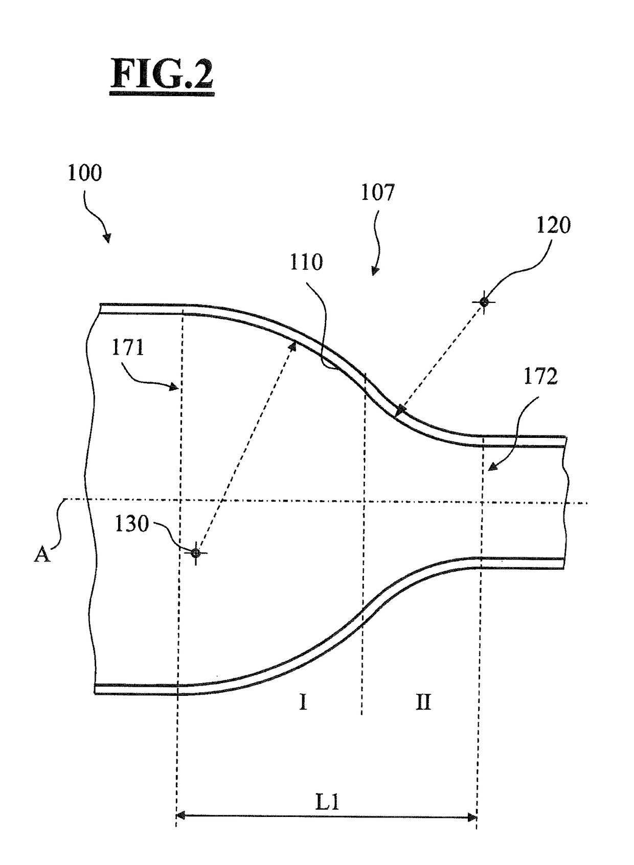
[0033]FIG. 2 shows a front part of the handpiece according to the invention. This handpiece also has a funnel-shaped region, see reference sign 107, which has a first zone I and a second zone II. Here, the second zone II is formed analogously to the funnel-shaped region 7 in accordance with FIG. 1 by virtue of this region 7 having an internal contour which is oriented toward the central axis A of the aspiration line 2 in such a way that an associated center of curvature 120 is oriented toward an end 172 of the funnel-shaped region 107. However, the first zone I is configured in such a way that a center of curvature 130 associated therewith is arranged on an opposite side in relation to the position of the center of curvature 120 of the second zone II. Therefore, the center of curvature 130 is not oriented toward the tapering end 172 of the funnel-shaped region 107, but rather in a direction toward an opening zone 171 of the funnel-shaped region 107, wherein the opening zone 171 is a...
third embodiment
[0034]FIG. 3 schematically shows a cross-section of a front part of the handpiece according to the invention. A funnel-shaped region 207 with an opening zone 271 and an end 272 is embodied in such a way that an associated internal wall contour 210 has a free-form contour. If this free-form contour is embodied appropriately, there are no eddies, and so a high concentration of the energy emitted by the drive element 5 can be achieved in the direction toward the distal end 9 of the needle 10.
[0035]FIG. 4 depicts a needle 10 of the handpiece 1 according to the invention, wherein isobars (IB1, IB2, IB3) have additionally been plotted. When calculating the isobars, the following boundary conditions were considered:
[0036]Ultrasound wave speed in the aspiration fluid: c0=1484 m / s
[0037]Ultrasonic frequency of the drive elements: f0=40 000 Hz;
[0038]Ultrasound wavelength in the aspiration fluid:
[0039]l0=c0 / f0=37.1 mm;
[0040]Amplitude of the drive elements: a0=50 μm.
[0041]Taking into account the...
PUM
 Abstract
Description
Claims
Application Information
 - R&D
- Intellectual Property
- Life Sciences
- Materials
- Tech Scout
- Unparalleled Data Quality
- Higher Quality Content
- 60% Fewer Hallucinations
Browse by: Latest US Patents, China's latest patents, Technical Efficacy Thesaurus, Application Domain, Technology Topic, Popular Technical Reports.
© 2025 PatSnap. All rights reserved.Legal|Privacy policy|Modern Slavery Act Transparency Statement|Sitemap|About US| Contact US: help@patsnap.com


