Eureka AIR delivers breakthrough ideas for toughest innovation challenges, trusted by R&D personnel around the world.

Conveying device for automation production lines

Active Publication Date: 2013-03-14
EBZ SYSTEC
View PDF1 Cites 3 Cited by
  • Summary
  • Abstract
  • Description
  • Claims
  • Application Information

AI Technical Summary

Benefits of technology

The invention helps to significantly decrease the time it takes to transport conventional systems because the positioning of the component carrier truck happens naturally during transportation in all directions (X / Y / Z). Lowering or lifting for fixing purposes is not necessary. The system also allows for faster acceleration and deceleration and overall transport speed. This avoids multiple travels over individual positioning means or positioning devices because only the responsible positioning means and devices come into mutual contact.

Problems solved by technology

Lowering or lifting for fixing purposes is unnecessary.

Method used


Image

  • Conveying device for automation production lines
  • Conveying device for automation production lines
  • Conveying device for automation production lines

Examples


Embodiment Construction

[0024]The exemplary embodiments illustrated show various technical details of the conveying device according to the invention, although these are not conclusively restricted solely to the exemplary embodiment shown, so that the different positionings can in each case be independently interchanged and implemented in the individual embodiments, insofar as is technically possible and expedient, by means of different positioning devices and positioning means, in order to fulfill the correspondingly required positioning and to be adaptable to possibly already existing plant technology.

[0025]Furthermore, equivalent parts are given the same reference symbols throughout, without being mentioned once more in particular in the respective figure descriptions.

[0026]To illustrate the space direction more clearly, coordinate axes are added to the individual figures, insofar as is necessary.

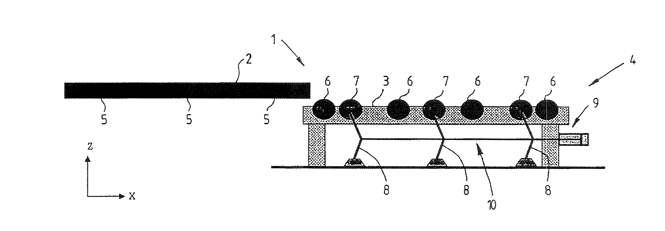
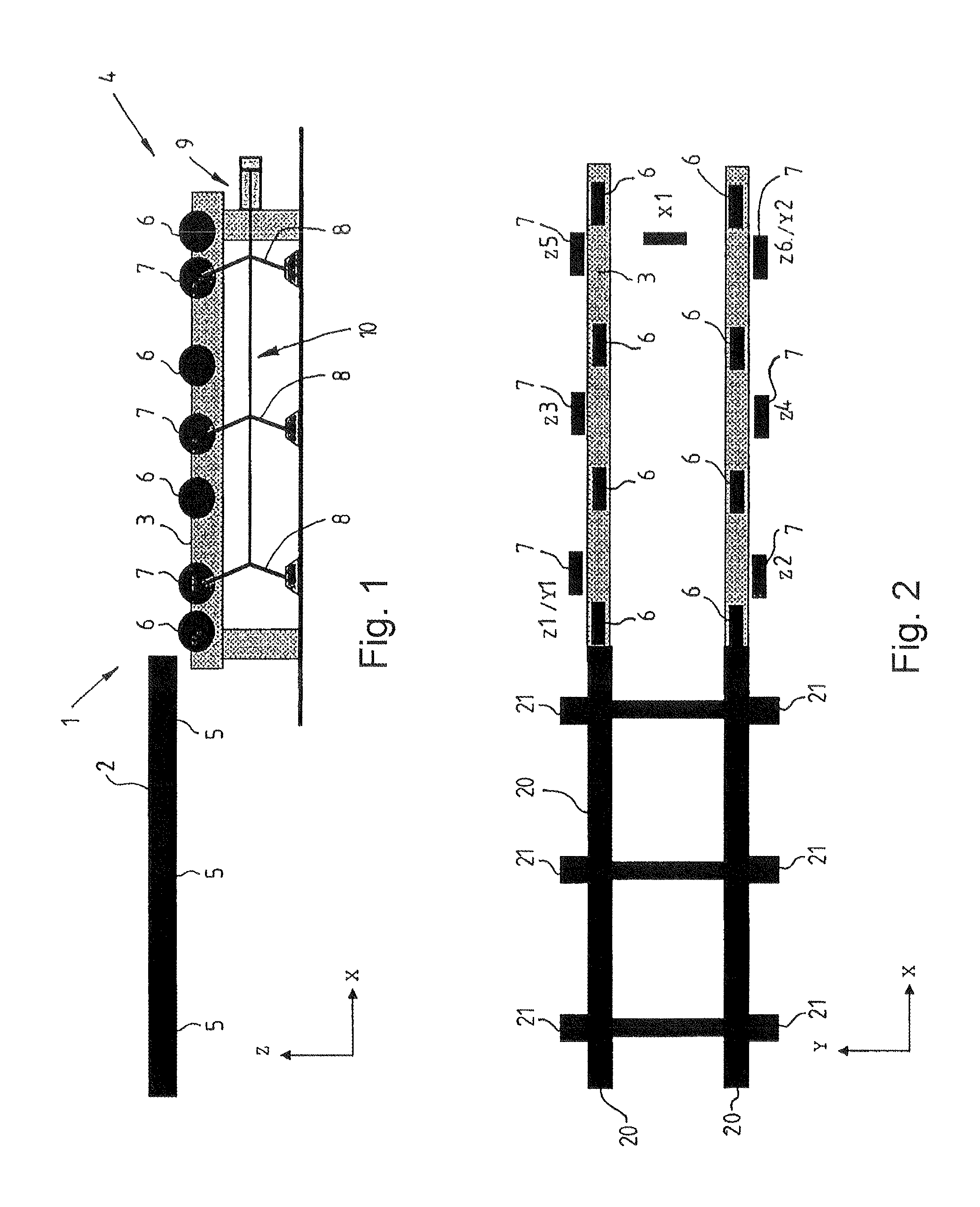
[0027]FIG. 1 shows a diagrammatic side view of a conveying device 1 according to the invention in which a co...


PUM


Abstract

The invention relates to a conveying device for the transport of components or component groups from and to one or more workstations, the conveying device comprising a conveying track and a component carrier truck moved on the conveying track, and there being provided in the region of the workstations, on the conveying track, positioning devices which cooperate with positioning means on the component carrier truck in such a way that a desired position of the component carrier truck in the workstation is assumed in all three space directions (X, Y, Z) directly as a result of the travel-in movement of the component carrier truck into the workstation, characterized in that, during the entire travel-in movement of the component carrier truck into the workstation, each positioning means on the component carrier truck comes into contact with only its positioning device, determining the desired position, on the conveying track.

Description

CROSS REFERENCE TO RELATED APPLICATIONS[0001]This application is a continuation of International Application No. PCT / EP2011 / 001974 filed Apr. 19, 2011, which designated the United States, and claims the benefit under 35 USC §119(a)-(d) of German Application No. 10 2010 015 618.3 filed Apr. 19, 2010, the entireties of which are incorporated herein by reference.FIELD OF THE INVENTION[0002]The invention relates to a conveying device for the transport of components or component groups from and to one or more workstations on an automation production line.BACKGROUND OF THE INVENTION[0003]Particularly in what is known as the carcass assembly of vehicle bodies, the various body parts are connected to one another at a plurality of workstations with the aid of robots by means of spot welds or other connection methods. The robots are in this case programmed such that they make their connections at exactly defined space coordinates. The task of a conveying device which makes the individual comp...

Claims


Application Information

Patent Timeline
IPC IPC(8): B62D65/18B65G47/24
CPCB65G47/24B62D65/18
Inventor STADLER, RAINERSCHMEH, ALEXANDER
Owner EBZ SYSTEC
Why Eureka
Eureka Blog
Learn More