Eureka AIR delivers breakthrough ideas for toughest innovation challenges, trusted by R&D personnel around the world.

Food portioning and application system

Inactive Publication Date: 2007-01-11
LUNGHI DONALD G
View PDF28 Cites 6 Cited by
  • Summary
  • Abstract
  • Description
  • Claims
  • Application Information

AI Technical Summary

Benefits of technology

[0009] The slices need to be neatly stacked or shingled when deposited on the targets and, for efficiency, the operation of slicing and depositing must be very rapid. The assumption here is that the meat logs are fed to the slicer with little or no interruption as the slicer transcends from log to log. To achieve the precision for deposit and neatness of the stacks or shingles, the preferred applicator incorporates a “Bomb Bay” type receiving grid. The grid is movable in the X, Y and Z axes. The Y axis allows the grid to move cross way to the conveyor to enable the grid to overlie different rows of targets. The X axis enables the grid to shift lengthwise relative to the conveyor which enables the grid to build shingled rather than stacked slices. The Z axis enables lowering of the grid to maintain a desired distance relative to the slicer during stacking. It is desired that the slices gravity fall from the slicer onto the grid or top most slice of a stack of slices from a short distance, e.g. about the thickness of a slice. The Z axis of movement enables the grid to accommodate that desire and to continuously shift up and down with each slice.
[0010] The X and Z movements of the grid provide for a neatly arranged stack and / or shingled arrangement of the slices and the Y axis enables positioning of the grid over multiple rows of targets. The application or deposit of the slices on the target tray or bun is accomplished by the Bomb Bay type release of the slices by the grid. The grid (in its preferred form) is in two parts and has hinge-like movement at opposed outer edges. The inner edges, in closed or receiving positions, are adjacent and define a center line of the grid to provide full support of the slices on the grid when closed. When the sliced food stack is to be deposited onto a tray or bun, the two parts of the grid are rapidly opened via the outer edge hinges and the slices are simply gravity dropped onto the tray / bun.

Problems solved by technology

A problem of the operation described above is the need for the first conveyor.
Nevertheless, there is a delay in the slicing operation, as one log is completely sliced, and the following log is fed into the slicer.
This causes feeding problems, e.g. for the last inch or so of the log end.
Further, even if the first conveyor were eliminated, the applicators developed for deposit of the food slices from the first conveyor to the trays cannot simply be mounted on the slicer mechanism and what is still needed is an applicator which will receive the slices sequentially, build the stack or shingled arrangement, and directly deposit those stacked portions and slices onto the targeted trays or buns.

Method used


Image

  • Food portioning and application system
  • Food portioning and application system
  • Food portioning and application system

Examples


Embodiment Construction

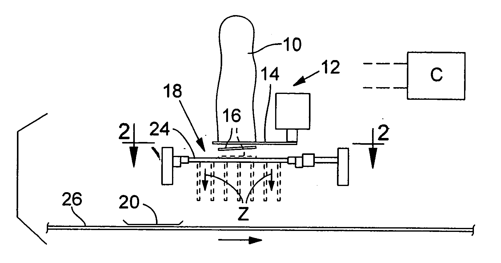
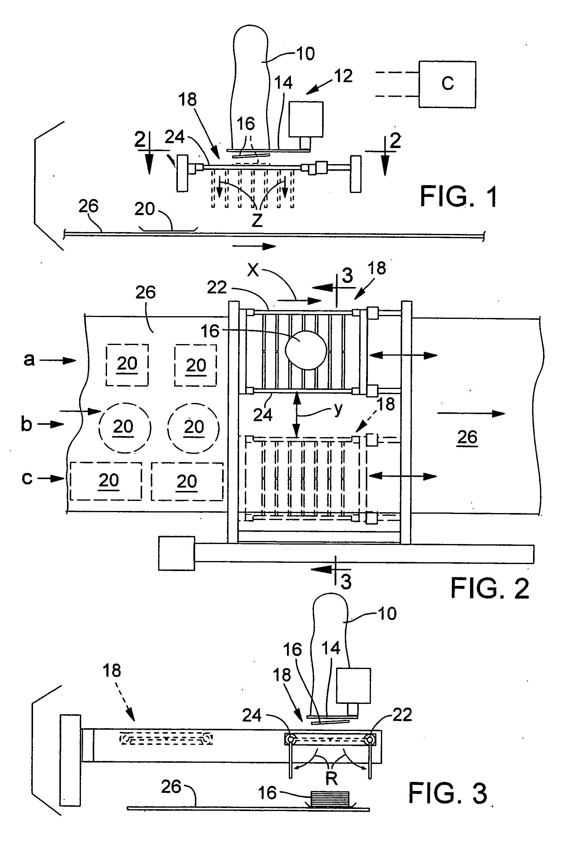
[0017] Reference is first made to FIGS. 1-3. In FIG. 1 a meat log or log is indicated as reference no. 10. A slicing machine 12 includes a pivoting or rotating blade 14 that slices through the log 10 to produce slices 16.

[0018] The slicing machine described is known and will not be illustrated or described in further detail. In a preferred embodiment, the log is gripped at opposed sides by feed conveyors and incrementally fed downward into the path of the blade 14. That is, the log is advanced downward by the desired thickness of a slice, the blade 14 is activated to cut through the log and thereby produce the slice 16 and that process is repeated over and over. Whereas, the schematic illustration of the log indicates that the log is advanced in the vertical direction and the blade pivoted through the log horizontally, it is common for the log to be in an angled position and the blade path angled accordingly. Either set up or arrangement will suffice for this application, but the v...


PUM

PropertyMeasurementUnit
Thicknessaaaaaaaaaa
Gravityaaaaaaaaaa

Abstract

A system for packaging slices from a slicer that slices food slices from a food log or log. Included is a conveyor conveying food slice receptacles (targets) and an applicator in the form of a Bomb Bay type receiving / dispensing grid. The grid includes opposing edges that define opposing hinges and the grid further includes paired grid halves respectively pivoted about their hinges. In a closed position the grid receives slices from the food log and in an open position dispenses the slices onto the targets of the conveyor. The grid includes vertical movements for controlling the position of the receiving surface receiving slices from the log, and lateral movements for varying the slice arrangement as between stacked and shingled arrangement, and for positioning such arrangements crossway of the conveyor for placement on the targets.

Description

FIELD OF THE INVENTION [0001] This invention relates to food packaging and more particularly to an automated procedure for slicing logs or logs of food items (e.g. meat or cheese logs or whole muscle meats) and placing the slices in selected different arrangements (e.g. multiple slices that are stacked or shingled) and in such a selected arrangement, depositing the arrangement of slices precisely on or in a receptacle (e.g. a tray or bun for building a sandwich). BACKGROUND OF THE INVENTION [0002] It is common to package trays of presliced meats such as bologna, ham, beef. chicken, turkey and the like. The product is either in whole muscle form or prepared first as elongate logs which are then sliced into desired thicknesses, e.g. suitable for sandwiches. The stacked or shingled arrangements may then be placed in trays which are sold as cutlets for prepared meals or wrapped for display and sale in grocery stores and the like. Alternatively, certain food outlets will sell a prepared ...

Claims


Application Information

Patent Timeline
IPC IPC(8): B26D7/00B26D7/20
CPCB26D7/32Y10T83/9312Y10T83/222
Inventor LUNGHI, DONALD G.
Owner LUNGHI DONALD G
Why Eureka
Eureka Blog
Learn More