
System and method for controlling pressure in a surgical tourniquet using a remote unit

a technology of remote unit and control device, which is applied in the field of surgical tourniquet controllers, can solve the problems of affecting the suitability of operator control, display, or interface, size and configuration of the controller, and the controller itself may be a problem, so as to reduce the involvement of the surgical tourniquet operator

Inactive Publication Date: 2007-11-01
STRYKER CORP +1
View PDF34 Cites 10 Cited by
  • Summary
  • Abstract
  • Description
  • Claims
  • Application Information

AI Technical Summary

Benefits of technology

The present invention is a surgical tourniquet controller that allows a surgeon to control the inflation of a surgical tourniquet from a remote location, reducing the need for the surgeon to be present near the tournicket. The controller includes a flow control unit with a pressure control valve for regulating the pressure in the tournicket. The controller also has a communications interface for receiving data from the remote unit and can include a redundant operator interface for increased safety. The invention allows for the control of surgical tourniquet performance with greater precision and efficiency, and can be used in a variety of surgical procedures.

Problems solved by technology

Additionally, the proximity of the surgical tourniquet controller to the surgical field results in the size and configuration of the controller having an effect on procedures within the surgical field.
Reducing the size of the controller may reduce the impact the physical proximity of the controller to the surgical field will have, however may also adversely affect the suitability of the operator controls, displays, or interface.
Finally, the configuration of the controller itself may be an issue in ensuring cleanliness in the area proximate to the surgical field.
Including additional personnel in the operating environment, however, may also increase congestion for other personnel in the environment.
Excesses of cabling may also be also undesired, due to the added complexity of ensuring that the cabling is accurately routed and connected, due to cleanliness issues associated with the cabling, and due to potential impacts the cabling may have on the operating environment, such as the creation of trip hazards.

Method used


Image

  • System and method for controlling pressure in a surgical tourniquet using a remote unit
  • System and method for controlling pressure in a surgical tourniquet using a remote unit
  • System and method for controlling pressure in a surgical tourniquet using a remote unit

Examples


Embodiment Construction

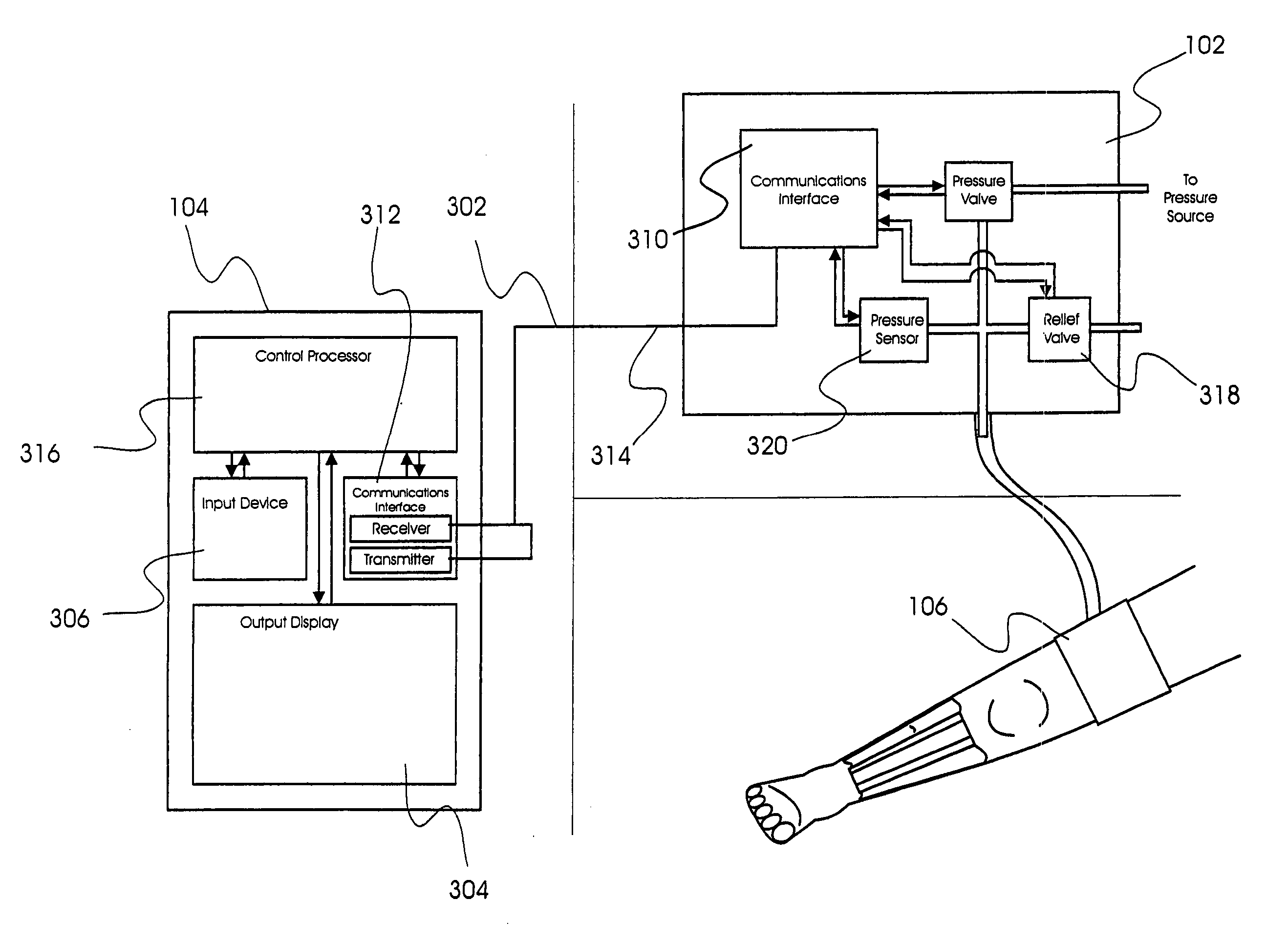
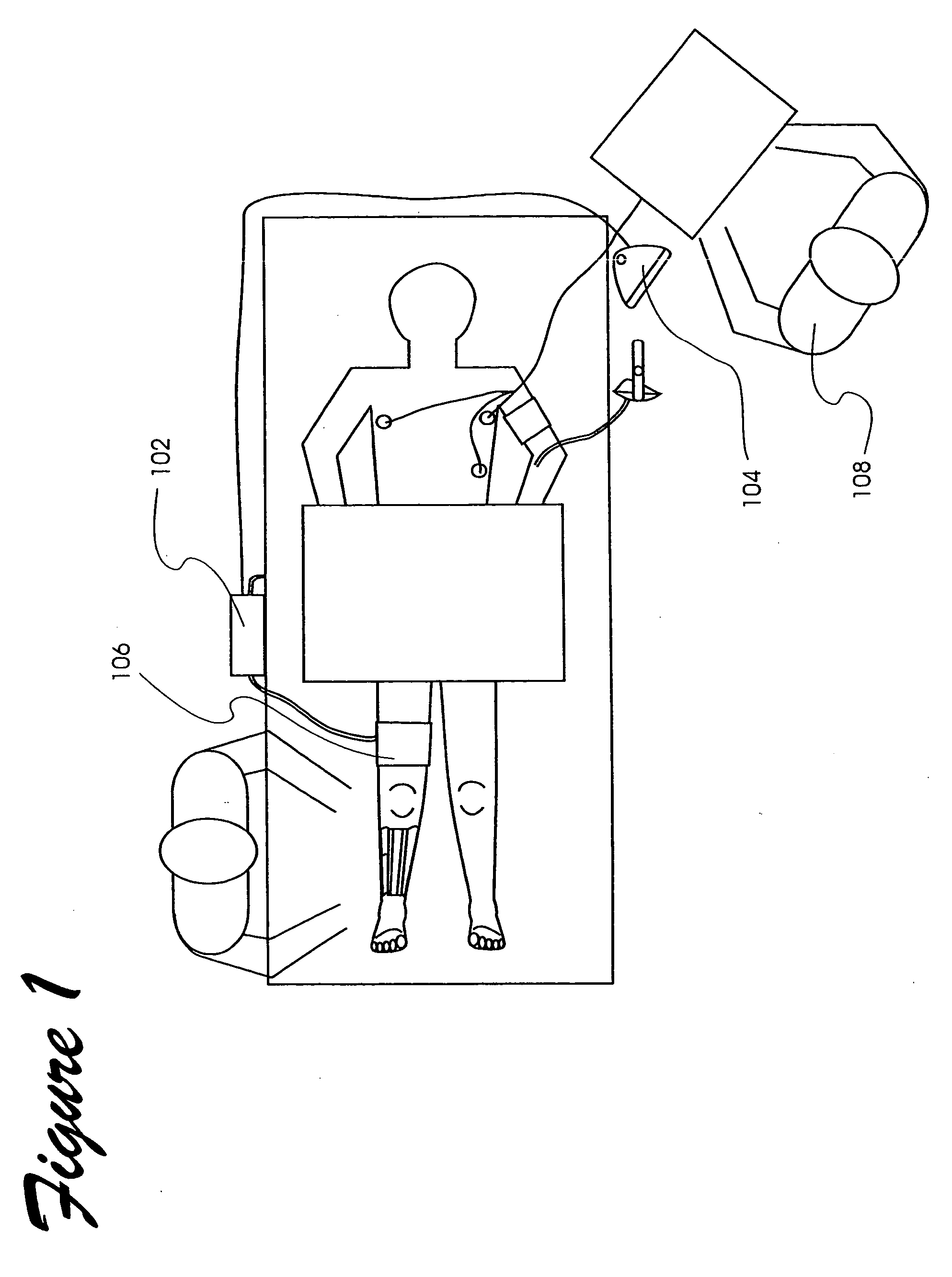
[0029] Referring particularly to FIG. 1, wherein like numerals represent like elements, there is shown a basic embodiment of a surgical tourniquet control system (hereafter “STCS”) embodying the present invention. A flow control unit 102 and a remote unit 104 are provided. The flow control unit 102 (hereafter “FCU”) may include flow control valves for controlling the pressure in a pressure cuff 106. Control circuitry for operating the valves may also be located in the FCU 102. The remote unit 104 provides an interface between an operator 102 of the surgical tourniquet control system and the flow control aspects of the system.

[0030] As shown in FIG. 1, the remote unit 104 may comprise a remote unit separate from the FCU 102 such that the remote unit 104 can be co-located with an anesthesiologist or other medical personnel 108 (hereafter referred to collectively as the “operator”). By providing the remote unit 104 at a location co-located with the operator 108 (such as when the anest...


PUM


Abstract

The present invention is a surgical tourniquet controller which receives operational parameters from a remote unit, allowing flow components associated with controlling a surgical tourniquet to be collocated with a surgical tourniquet in use, while allowing an operator of the tourniquet to operate the flow components from a remote location, such as at an anesthesiologists position, thus reducing the involvement of the surgical tourniquet operator from the surgical field.

Description

[0001] The present application is a continuation of U.S. patent application Ser. No. 10 / 290,117, which is a continuation in part of U.S. patent application Ser. No. 09 / 504,131, which is a continuation of U.S. patent application Ser. No. 09 / 280,312. U.S. patent application Ser. No. 09 / 280,312 issued as U.S. Pat. No. 6,051,016 on Apr. 18, 2002. U.S. patent application Ser. No. 10 / 290,117 issued as U.S. Pat. No. ______ on ______. The entire disclosures of these applications are incorporated herein in there entireties by reference thereto.FIELD OF THE INVENTION [0002] The present invention is directed to surgical tourniquet controllers, and more particularly to surgical tourniquet controllers having spatially separated operator control interfaces and fluid pressure controllers to allow management of equipment and operators adjacent to the surgical field. BACKGROUND [0003] Surgical tourniquets are used to provide a bloodless field for surgical procedures involving the extremities of the ...

Claims


Application Information

Patent Timeline
Patent Type & Authority Applications(United States)
IPC IPC(8): A61B17/132A61B17/135
CPCA61B17/1355A61B2017/00199A61B19/50A61B34/10
Inventor HOVANES, MICHAELSCHMITT, DON
Owner STRYKER CORP
Learn More