Multiview autostereoscopic display

a multi-view, auto-stereoscopic technology, applied in the field of multi-view auto-stereoscopic display, can solve the problems of improper viewing of three-dimensional images, narrow viewing zone of conventional three-dimensional image apparatus, and less than half the full resolution of display panel

Inactive Publication Date: 2007-11-08
SAMSUNG ELECTRONICS CO LTD
View PDF11 Cites 70 Cited by
  • Summary
  • Abstract
  • Description
  • Claims
  • Application Information

AI Technical Summary

Benefits of technology

[0007]Exemplary embodiments of the present invention overcome the above disadvantages and other disadvantages not described above. Also, the present invention is not required to overcome the disadvantages described above, and an exemplary embodiment of the present invention may not overcome any of the problems described above. Exemplary embodiments of the present invention provide a multiview autostereoscopic display that extends a viewing zone of a viewer and enables a viewer to see an autostereoscopic image even when the position of the viewer changes.

Problems solved by technology

Since the left eye image and the right eye image area are displayed on the same display panel, however, there is a problem in that the resolution of each image is not more than half the full resolution of the display panel.
However, a conventional three dimensional image apparatus has a very narrow viewing zone because the conventional three dimensional image apparatus only provides the image in two viewpoints.
Thus, when a viewer moves his head, the left and right images are reversed so that the viewing of a three dimensional image is improper.
However, the eye-tracking method has the limitation of only applying to a single viewer.

Method used


Image

  • Multiview autostereoscopic display
  • Multiview autostereoscopic display
  • Multiview autostereoscopic display

Examples


Embodiment Construction

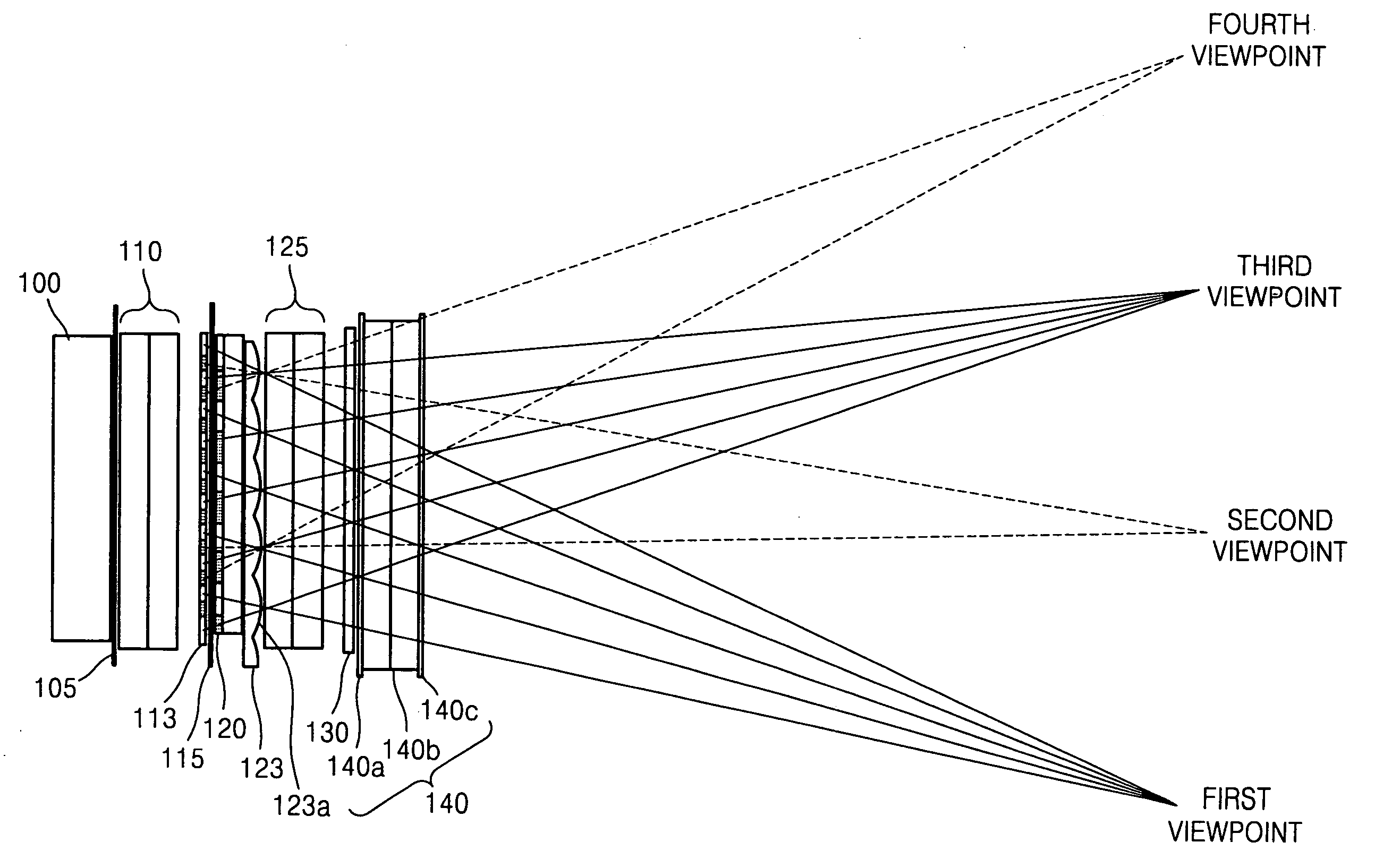
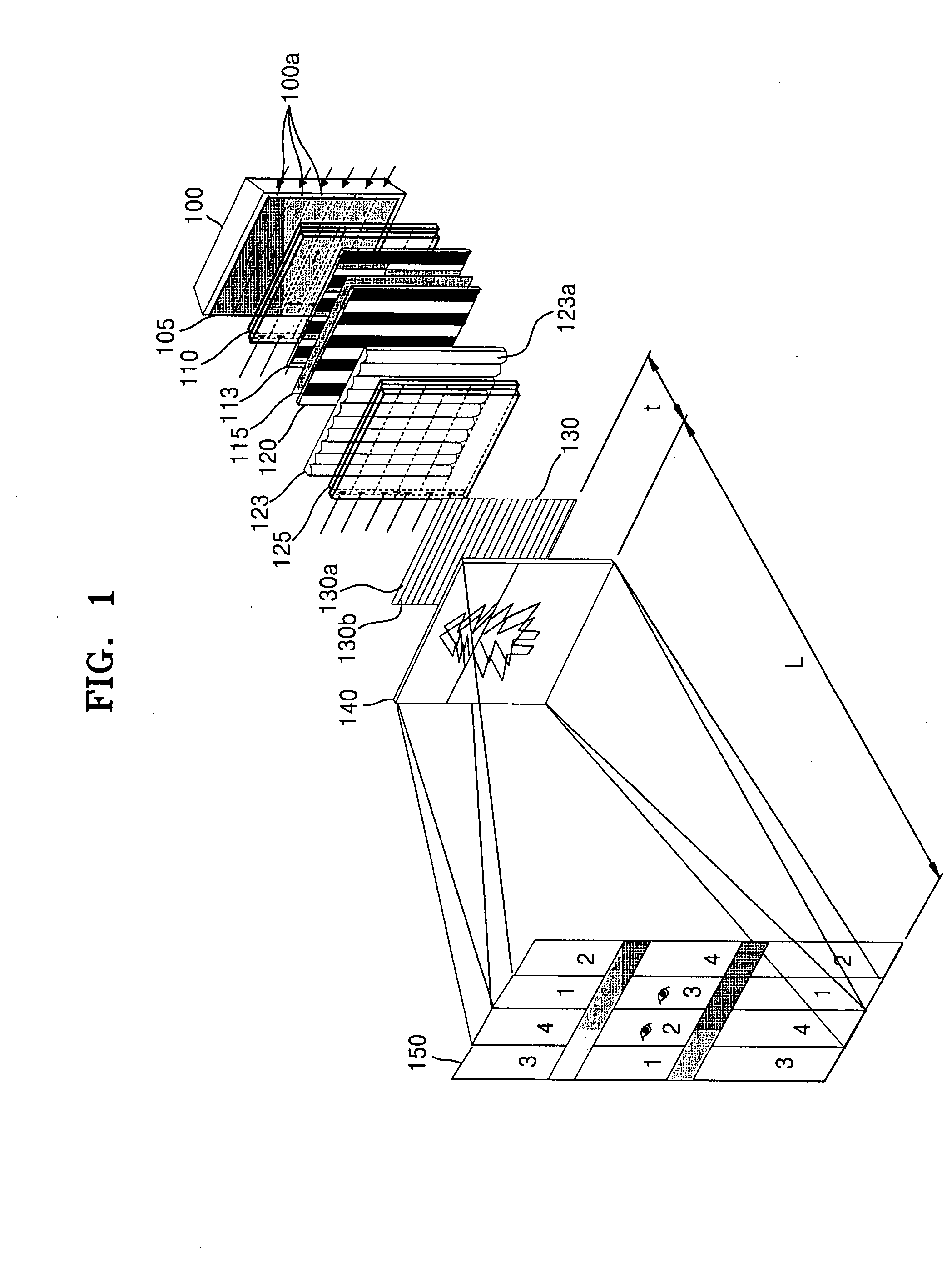
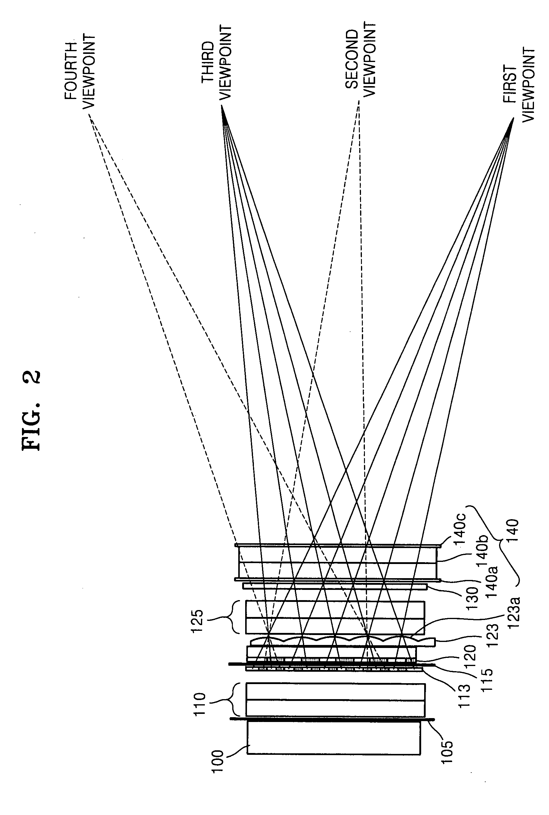
[0035]FIG. 1 illustrates a perspective view of a multiview autostereoscopic display according to an exemplary embodiment of the present invention. Referring to FIG. 1, the multiview autostereoscopic display according to the present embodiment includes a backlight unit 100; a first polarized panel 105 which only transmits the portion of the light from the backlight unit 100 which has a particular polarization direction; a first polarization switch 110 which changes the polarization direction of an incident beam by an electric control; and a first anisotropic device array 113.

[0036]The multiview autostereoscopic display also includes a second polarized panel 115 which, of the light emitted from the first anisotropic device array 113, only transmits light having a particular polarization direction; a second anisotropic device array 120; a lenticular lens array 123 which separates the incident beam into viewing zones; a second polarization switch 125 which changes the polarization direc...


PUM


Abstract

A multiview autostereoscopic display includes: a backlight; a first polarized panel transmitting light having a first polarization; a first polarization switch changing the polarization of incident light; a first anisotropic device array including anisotropic devices sequentially and repeatedly arranged in a horizontal direction, such that light transmitted from neighboring anisotropic devices has perpendicular polarizations; a lenticular lens array having lenticular lens devices, arranged horizontally, which separate incident light into different directions; a second polarized panel transmitting light having a second polarization; a second anisotropic device array having anisotropic devices alternately horizontally arranged, such that the anisotropic devices transmit light having perpendicular polarizations; a second polarized switch changing the polarization of light from the lenticular lens array; a third anisotropic device array having anisotropic devices, alternately vertically arranged, such that the anisotropic devices transmit light having perpendicular polarizations; and a display panel forming an image by modulating incident light.

Description

CROSS-REFERENCE TO RELATED PATENT APPLICATIONS[0001]This application claims the benefit of Korean Patent Application No. 10-2006-0067302, filed on Jul. 19, 2006, in the Korean Intellectual Property Office, and the benefit of U.S. Provisional Patent Application No. 60 / 797,372, filed on May 4, 2006, in the U.S. Patent and Trademark Office, the disclosures of which are incorporated herein in their entirety by reference.BACKGROUND OF THE INVENTION[0002]1. Field of the Invention[0003]The present invention relates to a multiview autostereoscopic display having an extended viewing zone enabling the viewer to see an autostereoscopic image from various positions.[0004]2. Description of the Related Art[0005]A binocular parallax method is an effective method for providing an autostereoscopic image in a flat panel display. The binocular parallax method provides a three dimensional image by separating the viewing zones of a left eye and a right eye of a stereopair in order to allow the left and ...

Claims


Application Information

Patent Timeline
Patent Type & Authority Applications(United States)
IPC IPC(8): G02B27/22H04N13/351G02B30/25
CPCH04N13/045H04N13/0404H04N13/305H04N13/32H04N13/354H04N13/349H04N13/351H04N13/00
Inventor SHESTAK, SERGEYKIM, DAE-SIKJUNG, SUNG-YONG
Owner SAMSUNG ELECTRONICS CO LTD
Why Eureka
Try Eureka