Methods and Apparatus for Processing a Pulsed Laser Beam to Create Apertures Through Microlens Arrays, and Products Produced Thereby

a laser beam and microlens array technology, applied in the field of microfabrication methods, can solve the problems of low throughput, non-uniform aperture, and widespread commercial use of laser beams to create self-aligned apertures through microlens arrays

Inactive Publication Date: 2007-11-08
BRIGHT VIEW TECHNOLOGIES CORPORATION
View PDF15 Cites 24 Cited by
  • Summary
  • Abstract
  • Description
  • Claims
  • Application Information

AI Technical Summary

Benefits of technology

[0008] In some embodiments, the pulsed laser beam is focused in the vacuum spatial filter under a vacuum of between about 50 mTorr and about 100 mTorr. In other embodiments, the pulsed laser beam is focused in the vacuum spatial filter under a vacuum that is configured to maintain a continuous plasma at a focal point of the pulsed laser beam. In other embodiments, the vacuum is also configured to prevent substantial absorption of the pulsed laser beam in the vacuum spatial filter.

Problems solved by technology

Despite the disclosure of self-aligned aperture formation techniques using a laser beam in the Deml et al. patent over 25 years ago, commercial use of laser beams to create self-aligned apertures through a microlens array do not appear to be widespread.
In particular, since a laser produces a relatively small beam of light, aperture creation processes for large substrates, such as substrates having at least one dimension that is about 30 inches or more, may provide low throughput.
Moreover, attempts to expand the size of the laser beam that impinges on the apertures may create lack of uniformity over the area of the expanded beam, which may result in the creation of non-uniform apertures.
Non-uniform apertures may, in turn, create unacceptable visible defects when the substrates are used in optical applications.

Method used


Image

  • Methods and Apparatus for Processing a Pulsed Laser Beam to Create Apertures Through Microlens Arrays, and Products Produced Thereby
  • Methods and Apparatus for Processing a Pulsed Laser Beam to Create Apertures Through Microlens Arrays, and Products Produced Thereby
  • Methods and Apparatus for Processing a Pulsed Laser Beam to Create Apertures Through Microlens Arrays, and Products Produced Thereby

Examples


examples

[0093] The following Examples shall be regarded as merely illustrative and shall not be construed as limiting the invention.

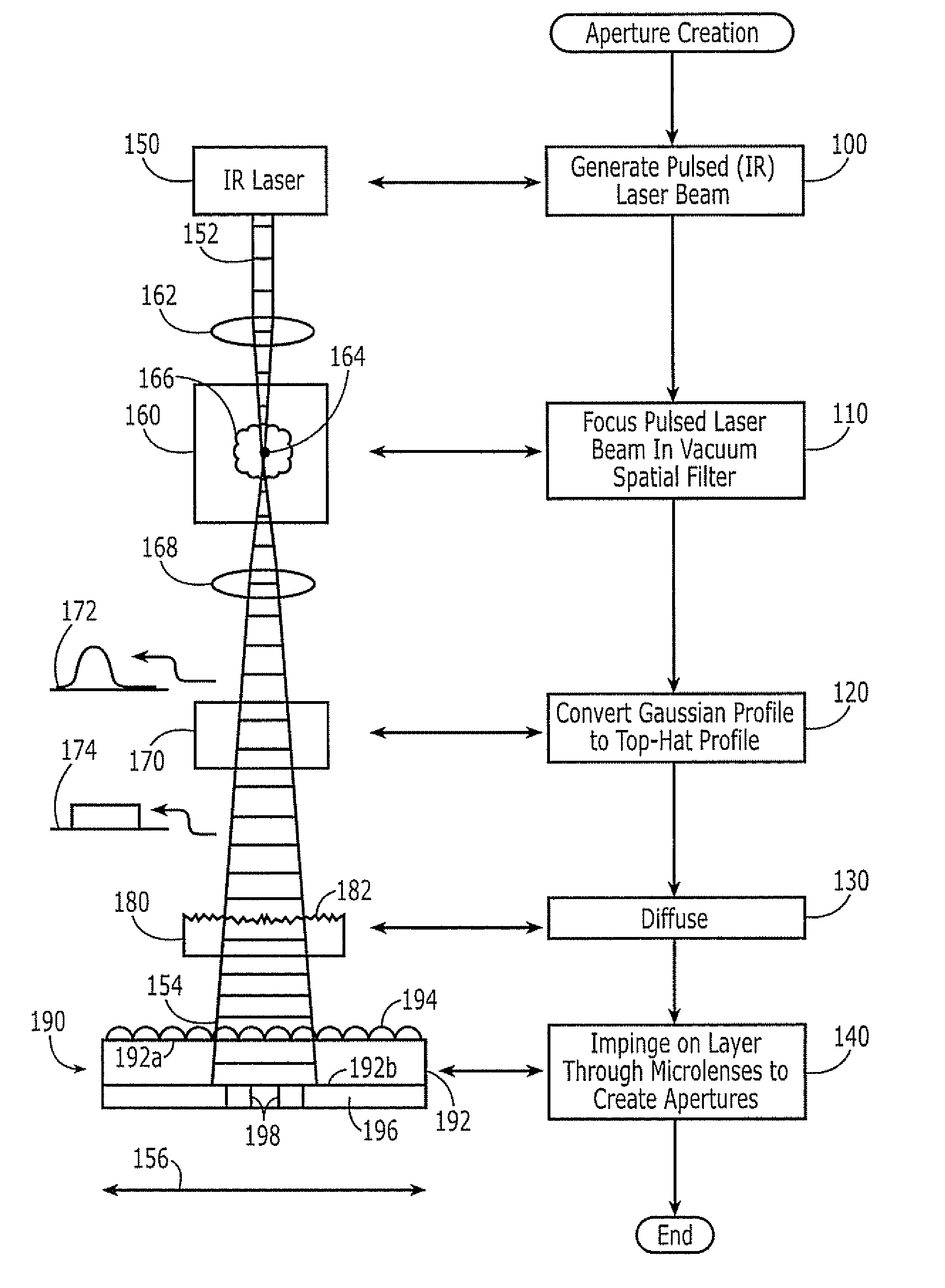
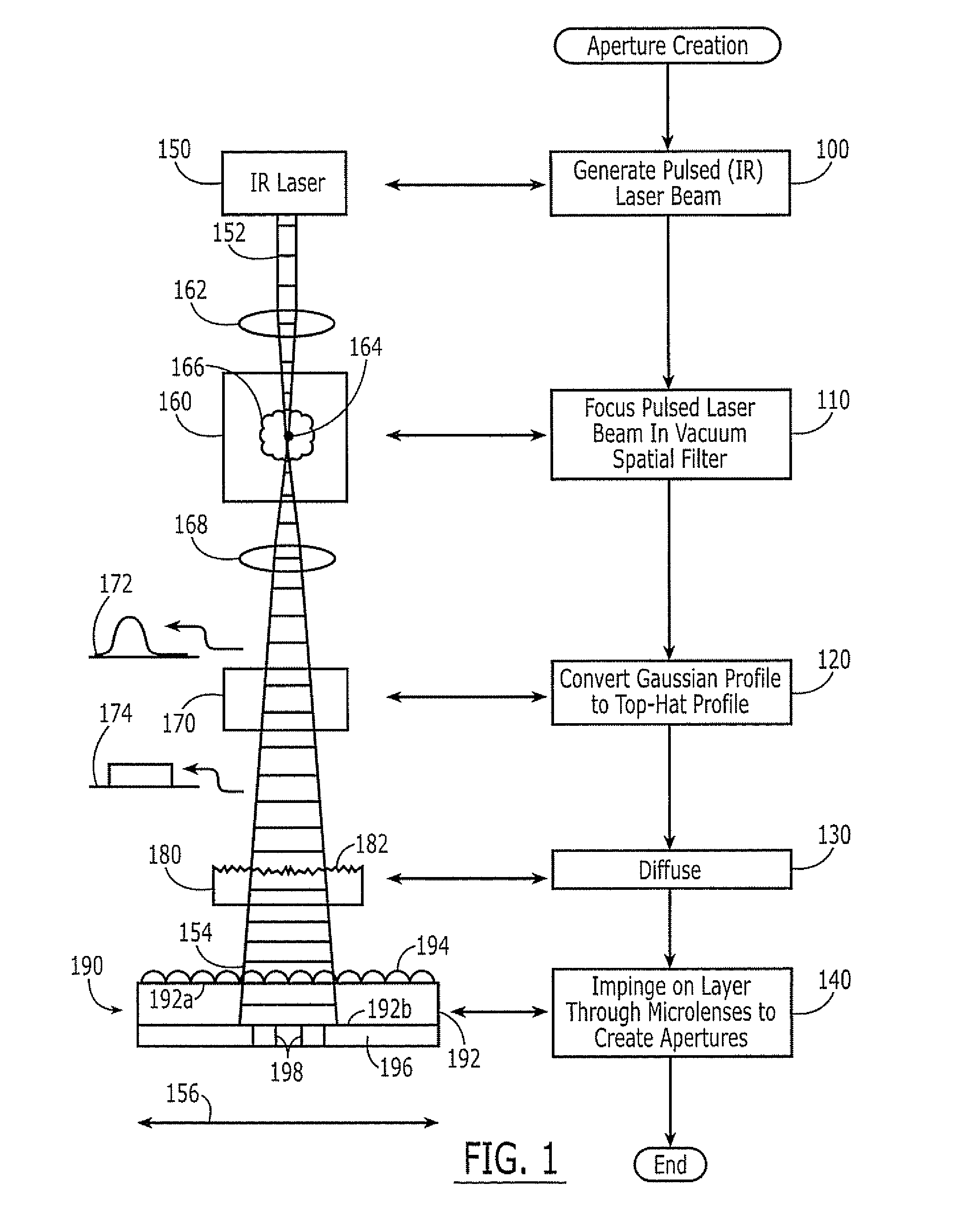
[0094] A laser 150 was configured as in FIG. 8. The top hat profile laser beam is directed to a mirror 840, and is reflected and traverses a distance of about 2 to about 50 feet. The beam then strikes a second mirror 850, which is mounted perpendicular to a rotary table. The rotary table oscillates between angles of + / −1 to about +−5 degrees to cause the beam 154 to scan over the surface to be exposed, which is positioned opposite this last oscillator mirror 850. Positioned between the last oscillating mirror 850 and the lens sheet 190 to be exposed is the diffuser element 180. As mentioned before, the amount of diffusive character of the element may have an impact on aperture creating.

[0095] Diffusive optical elements 180 can be acquired or created by known techniques. In this example, a glass sheet 180 was subject to a glass bead spray at 80 lb. pressure an...


PUM


Abstract

A pulsed laser beam is used to create apertures in a layer on a back side of a substrate that includes a microlens array on a front side thereof. The pulsed laser beam is focused in a vacuum spatial filter. A profile of the pulsed laser beam that emerges from the vacuum spatial filter is converted to a top hat profile. The laser beam having the top hat profile is diffused. Finally, the pulsed laser beam having the top half profile that has been diffused is impinged through the microlens array on the front side of the substrate and onto the layer on the back side of the substrate. Related apparatus for creating the apertures and microlens array products are also described.

Description

FIELD OF THE INVENTION [0001] This invention relates to microfabricating methods, apparatus and devices so fabricated, and more particularly to methods and apparatus for fabricating optical microstructures and optical microstructures fabricated thereby. BACKGROUND OF THE INVENTION [0002] Substrates having a microlens array on one side thereof and an array of self-aligned apertures on the other side thereof, are widely used as optical components in computer displays (monitors), projection televisions, flat panel displays and televisions, and many other optical applications. As is well known to those having skill in the art, a microlens array includes a large number of microlenses, at least one dimension of a base of which (a “base dimension”) is less than about 100 μm in size. Hemispherical, anamorphic, lenticular and / or other conventional microlens arrays may be formed. The self-aligned apertures may be created in a layer, such as an opaque and / or reflective layer, by impinging a la...

Claims


Application Information

Patent Timeline
Patent Type & Authority Applications(United States)
IPC IPC(8): G02B27/10
CPCG02B3/0056G02B27/0988G02B27/0927
Inventor GARDNER, RICHARD N.RINEHART, THOMAS A.WOOD, ROBERT L.
Owner BRIGHT VIEW TECHNOLOGIES CORPORATION
Why Eureka
Try Eureka