
Light-emitting module capable of increasing dispersion diameter

a technology of light-emitting modules and dispersion diameters, which is applied in the direction of lighting device details, lighting and heating apparatus, instruments, etc., can solve the problems of difficult to reduce the distance interval between the lcd panel and the led to a predetermined distance interval, and the diffusing plate and the diffusing sheet can be removed from the direct illumination type backlight assembly. , to achieve the effect of slimmer display devices

Inactive Publication Date: 2007-11-08
SAMSUNG ELECTRONICS CO LTD
View PDF14 Cites 39 Cited by
  • Summary
  • Abstract
  • Description
  • Claims
  • Application Information

AI Technical Summary

Benefits of technology

[0017]According to the light-emitting module and the display device of the invention, the optical cap sufficiently diffuses the light that is emitted from the point-light source so that extra components such as a diffusing plate, a diffusing sheet, etc., may be omitted from the display device and the display device may be slimmer.

Problems solved by technology

However, due to the light characteristics of the LED, it is difficult to remove the diffusing plate and the diffusing sheet from the direct illumination type backlight assembly.
Additionally, it is difficult to decrease the distance interval between the LCD panel and the LED to a predetermined distance interval.

Method used


Image

  • Light-emitting module capable of increasing dispersion diameter
  • Light-emitting module capable of increasing dispersion diameter
  • Light-emitting module capable of increasing dispersion diameter

Examples


Embodiment Construction

[0031]The invention is described more fully hereinafter with reference to the accompanying drawings, in which embodiments of the invention are shown. This invention may, however, be embodied in many different forms and should not be construed as limited to the embodiments set forth herein. Rather, these embodiments are provided so that this disclosure will be thorough and complete, and will fully convey the scope of the invention to those skilled in the art. In the drawings, the size and relative sizes of layers and regions may be exaggerated for clarity.

[0032]It will be understood that when an element or layer is referred to as being “on,”“connected to” or “coupled to” another element or layer, it can be directly on, connected or coupled to the other element or layer or intervening elements or layers may be present. In contrast, when an element is referred to as being “directly on,”“directly connected to” or “directly coupled to” another element or layer, there are no intervening e...


PUM


Abstract

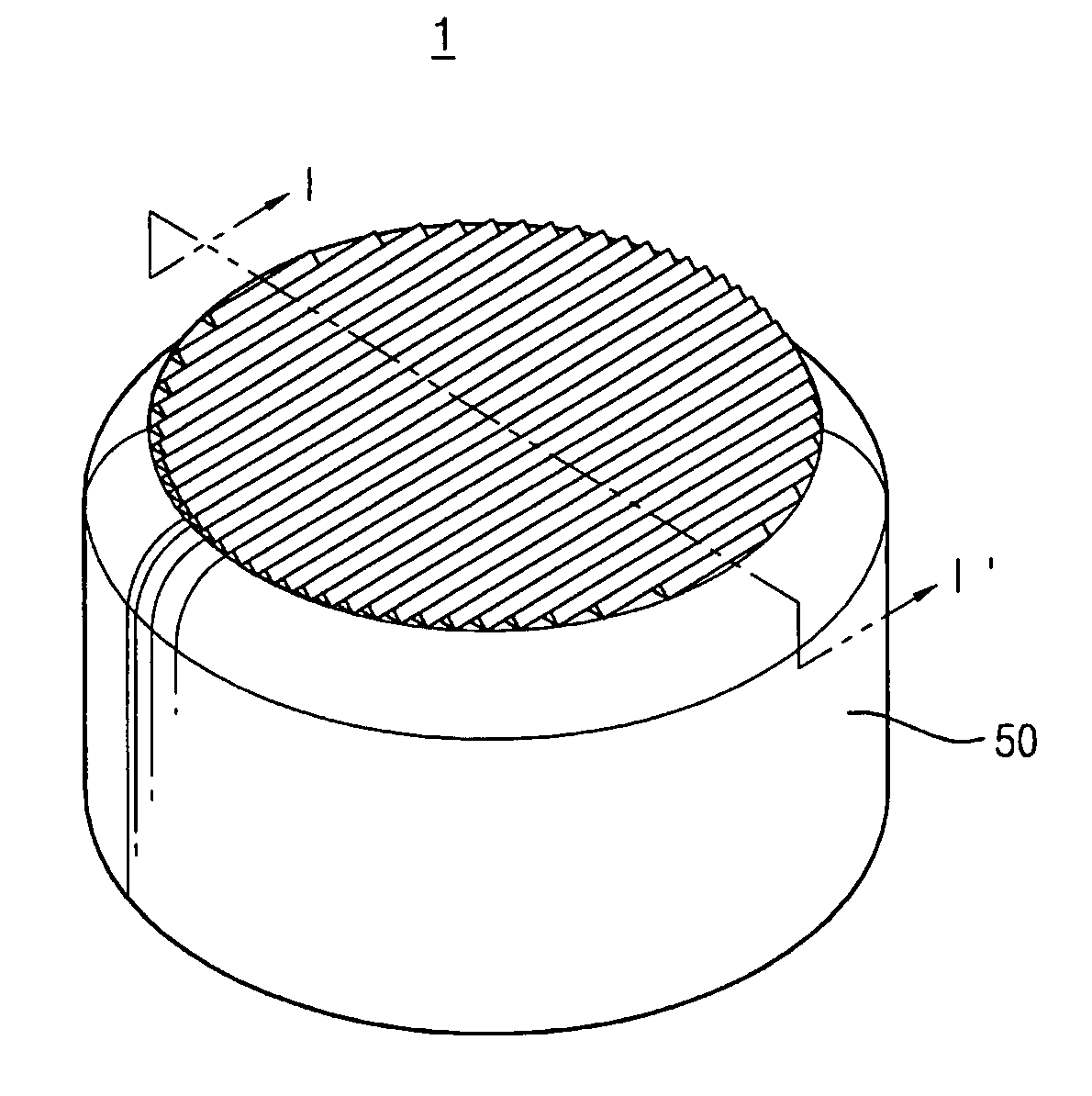
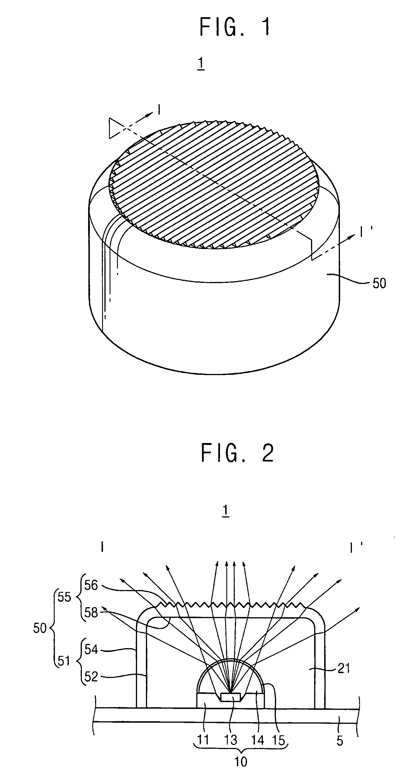
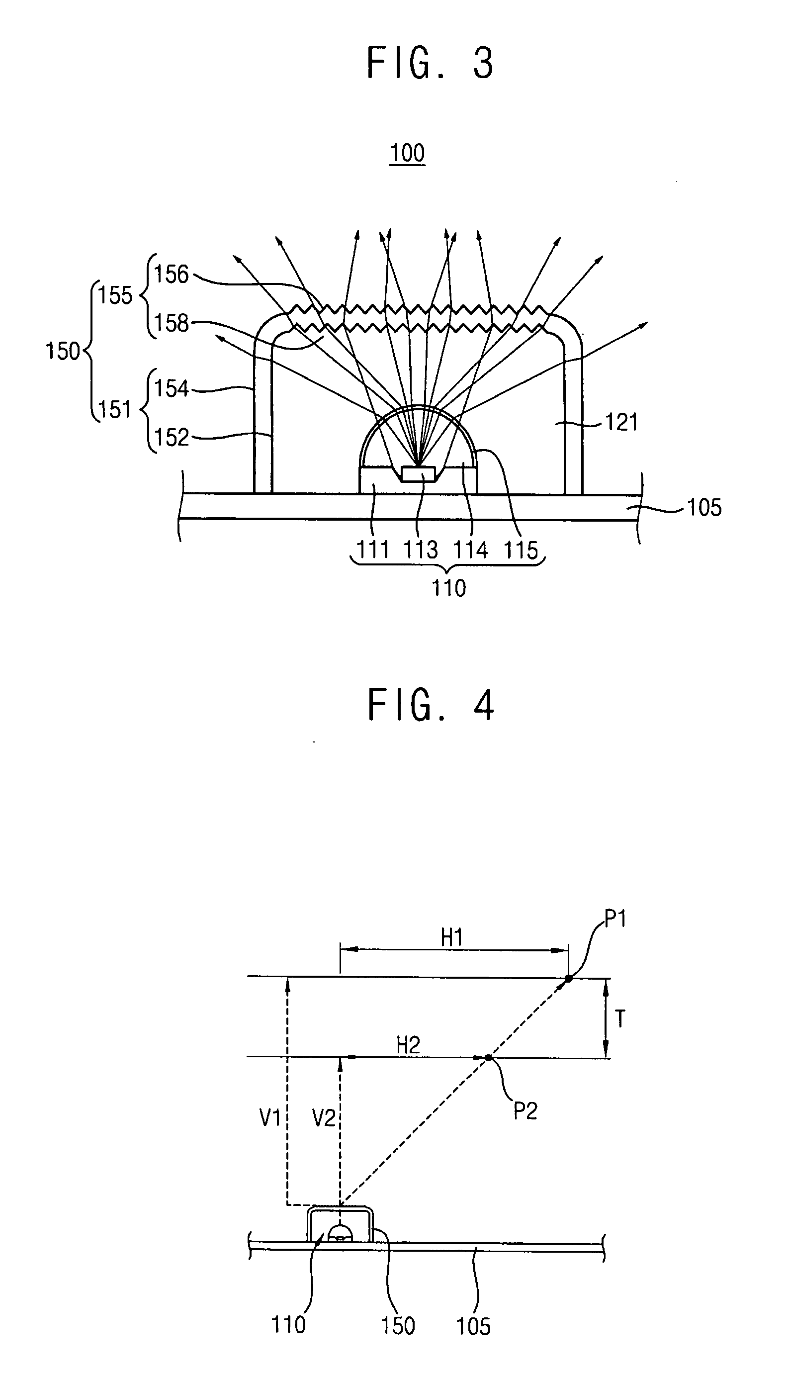
A light-emitting module that allows a display panel to be made thinner is presented. The light-emitting module includes a point-light source and an optical cap. The point-light source is disposed on a substrate. The optical cap surrounds a side portion and an upper portion of the point-light source and has a first embossing pattern formed thereon. Light is emitted from the point-light source and passes through the optical cap to be diffused, for example by the first embossing pattern. Thus, extra components such as a diffusing plate, a diffusing sheet, etc., may be omitted from the display device, and the display device may be slimmer.

Description

CROSS-REFERENCE TO RELATED APPLICATIONS[0001]This application claims priority to Korean Patent Application No. 2006-39531 filed on May 2, 2006 in the Korean Intellectual Property Office (KIPO), the content of which is herein incorporated by reference in its entirety.BACKGROUND OF THE INVENTION[0002]1. Field of the Invention[0003]The present invention relates to a light-emitting module and a display device having the light-emitting module. More particularly, the present invention relates to a light-emitting module capable of increasing a dispersion diameter of an emitted light and a display device having the light-emitting module.[0004]2. Description of the Related Art[0005]Generally, a liquid crystal display (LCD) panel does not emit light. Thus, to operate as a display device, an LCD device typically includes a backlight assembly that provides light to the LCD panel. The backlight assembly includes a light source and an optical unit that enhances the characteristics of the light fr...

Claims


Application Information

Patent Timeline
Patent Type & Authority Applications(United States)
IPC IPC(8): F21V5/00
CPCG02B5/0231G02B5/0242G02F1/133606G02B5/045G02F1/133603G02B5/0278
Inventor PARK, SE-KIYANG, BYUNG-CHOON
Owner SAMSUNG ELECTRONICS CO LTD
Learn More