Display device

a display device and display technology, applied in the field of display devices, can solve the problems of large thickness of a typical display device, inability to reduce the number of substrates, and disfavor the thinning of the display device, and achieve the effect of facilitating the subsequent control of light rays

Active Publication Date: 2018-07-05
BOE TECH GRP CO LTD +1
View PDF8 Cites 4 Cited by
  • Summary
  • Abstract
  • Description
  • Claims
  • Application Information

AI Technical Summary

Benefits of technology

[0022]In an embodiment of the present disclosure, by adding a light correction section in the display device, light rays emitted from the color control light-emitting units a

Problems solved by technology

Moreover, since the lower POL needs to be arranged on an outer side of the substrates, the substrates cannot be reduced in number.
This in turn results in a large thickness of a typical display device and disfavo

Method used


Image

  • Display device
  • Display device
  • Display device

Examples


Embodiment Construction

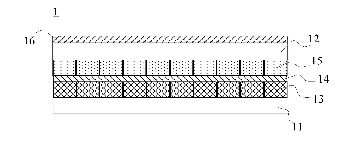
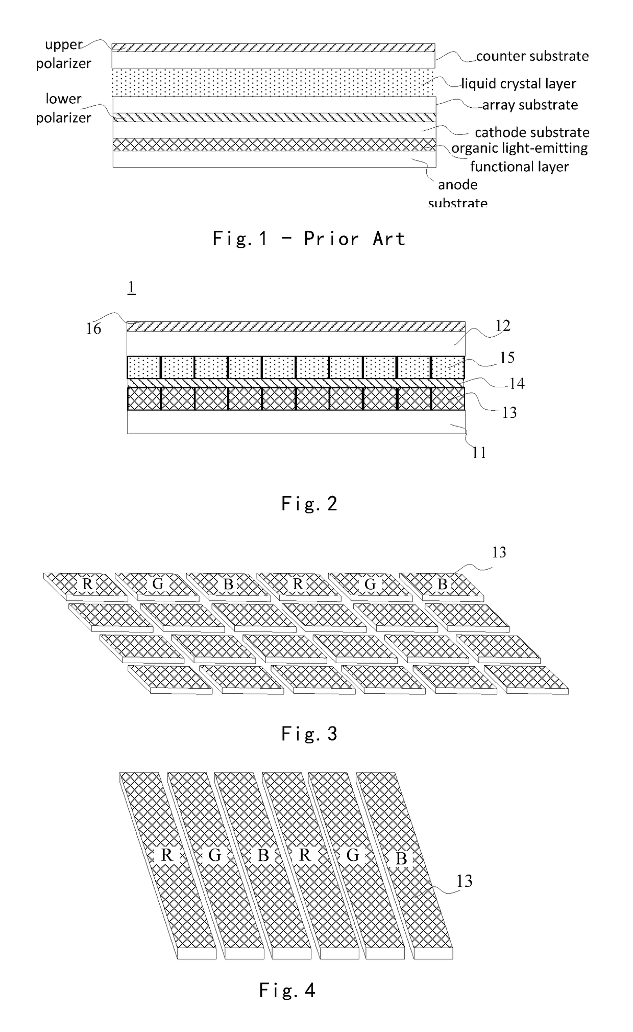
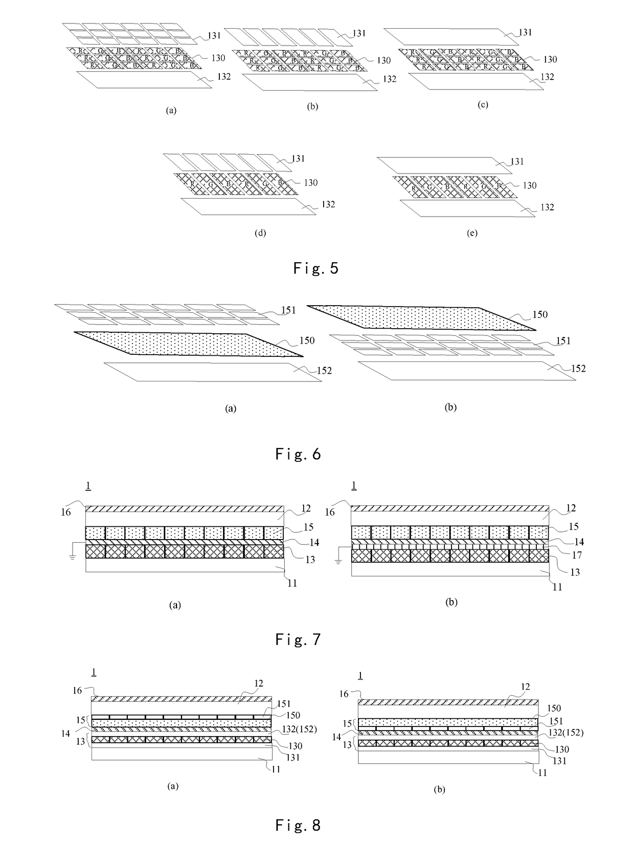
[0041]Reference signs are listed as follows:[0042]1—display device;[0043]11—first substrate;[0044]12—second substrate;[0045]13—color control light-emitting unit;[0046]130—light-emitting functional layer;[0047]131—anode;[0048]132—cathode;[0049]14—wire grid polarizer;[0050]15—transmittance adjustment pixel unit;[0051]150—liquid crystal layer;[0052]151—pixel electrode;[0053]152—common electrode;[0054]16—polarizer;[0055]17—transparent conductive layer;[0056]18—light correction section;[0057]40—diffraction grating;[0058]40a—grating surface;[0059]40b—groove surface;[0060]41, 51—first dielectric layer;[0061]41b—light exit surface of first dielectric layer;[0062]41b_1—refractive sub-surface;[0063]41b_2—connection sub-surface;[0064]42, 52—second dielectric layer.

[0065]Technical solutions in embodiments of the present disclosure will be described clearly and completely below with reference to drawings of embodiments of the present disclosure. Apparently, these embodiments described below are ...


PUM


Abstract

The present disclosure relates to the field of display technologies, and discloses a display device for reducing a thickness of the display device, so as to obtain a thinner display device and simplify the manufacture process. The display device includes a first substrate and a second substrate arranged oppositely; as well as a plurality of color control light-emitting units, a wire grid polarizer and a plurality of transmittance adjustment pixel units arranged sequentially from an inner side of the first substrate towards an inner side of the second substrate.

Description

[0001]The present application is the U.S. national phase entry of PCT / CN2016 / 095218, with an international filling date of Aug. 15, 2016, which claims the benefit of Chinese Patent Application No. 201610222445.3, filed on Apr. 11, 2016, the entire disclosures of which are incorporated herein by reference.FIELD[0002]The present disclosure relates to the field of display technologies, and in particular to a display device.BACKGROUND ART[0003]A typical display device comprises an Organic Light-Emitting Diode (OLED) light-emitting panel and a Liquid Crystal Display (LCD) light-regulating panel. In such a display device, the OLED light-emitting panel emits red light, green light and blue light. After that, the LCD light-regulating panel adjusts light transmittances of the incident red light, green light and blue light, thereby realizing display.[0004]Specifically, the OLED light-emitting panel comprises a substrate provided with an anode (also referred to as an anode substrate), a substr...

Claims


Application Information

Patent Timeline
IPC IPC(8): G02F1/1335H01L27/32
CPCG02F1/133528H01L27/32G02F1/1333G02F1/133504H10K59/35H10K59/50G02F1/133602G02F1/133603G02F1/133606G02F1/133548H10K59/38H10K59/00
Inventor WANG, QIANDONG, XUECHEN, XIAOCHUANLU, PENGCHENGNIU, XIAOCHENGAO, JIANYANG, MING
Owner BOE TECH GRP CO LTD
Why Eureka
Try Eureka