Diaphragm pump

Inactive Publication Date: 2007-11-08
YASUNAGA AIR PUMP
View PDF4 Cites 13 Cited by
  • Summary
  • Abstract
  • Description
  • Claims
  • Application Information

AI Technical Summary

Benefits of technology

[0014] In the diaphragm pump having the above structure, the suction-side check valve is arranged to have a space between the valve body and the valve seat, and hence functions as a normally-open check valve. By using this suction-side check valve in combination with the discharge-side check valve which functions as a normally-closed check valve, the time for which the suction-side check valve is open in the process of expanding the volume of the pressure chamber for sucking air from the suction port into the pressure chamber can be made longer, so that a load on the diaphragm can be reduced.
[0015] Since the load on the diaphragm is reduced, it is not necessary to apply part of the pressure in the pressure chamber to the diaphragm as a back pressure as in the conventional case, and hence, a complicated structure is not required. Further, even when the diaphragm pump is operated at a high operating pressure, the diaphragm can be caused to oscillate with certainty, since the load on the diaphragm is reduced as mentioned above. Thus, also when the diaphragm pump is operat

Problems solved by technology

When the operating pressure of the diaphragm pump is raised to obtain a high discharge pressure, however, a high pressure in the pressure chamber makes it difficult for the diaphragm to oscillate.
This easily causes variation in the time for which the suction-side check valve is open, and thereby makes the amount of a fluid sucked into the pressure chamber unstable.
The adoption of such arrangement, however, causes a problem that the casing (sealed space) containing the electromagnet requires a complic

Method used


Image

  • Diaphragm pump
  • Diaphragm pump
  • Diaphragm pump

Examples


Embodiment Construction

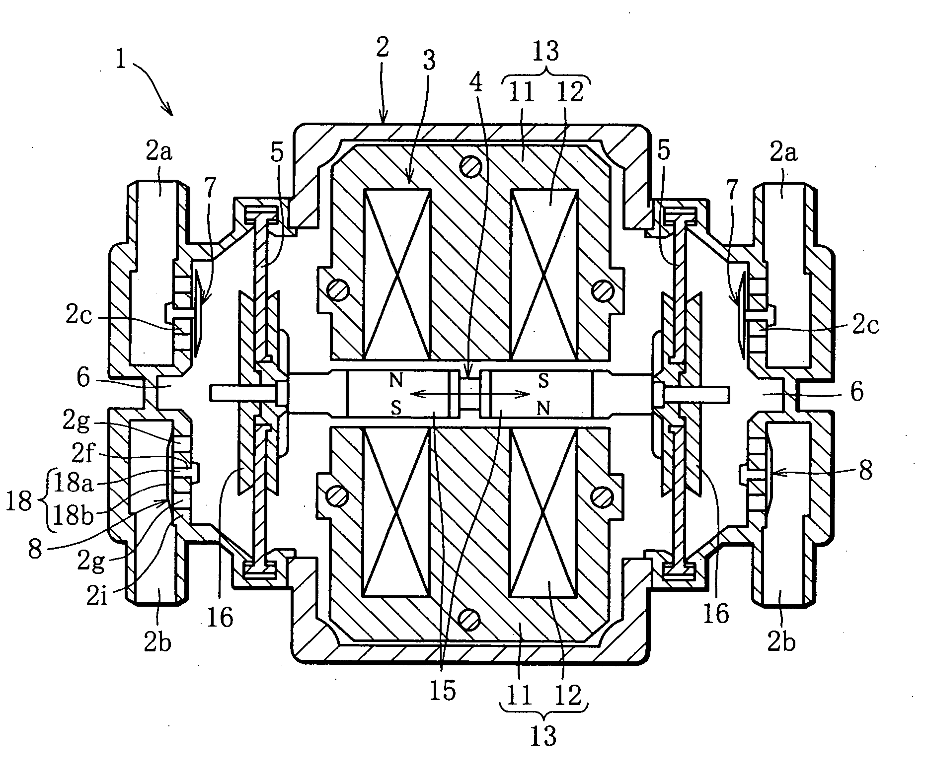
[0023] Referring to the drawings, an embodiment of this invention will be described, using an example of an electromagnetic diaphragm pump which is driven by an electromagnet to compress and discharge air.

[0024]FIG. 1 is a cross-sectional view schematically showing the structure of an electromagnetic diaphragm pump in an embodiment of this invention. The electromagnetic diaphragm pump 1 comprises a frame 2, an electromagnet 3 enclosed in the frame 2, a rod-like oscillator 4 driven by the electromagnet 3 to move back and forth in the axial direction, two diaphragms 5, 5 provided at the opposite ends of the oscillator 4, and paired pressure chambers 6, 6 provided outside the frame 2, each having one of the diaphragms 5, 5 as a wall. As described later, the paired pressure chambers 6, 6 are formed by paired casings 2c, 2c which are fitted to the frame 2 on both sides, in a manner covering each diaphragm 5.

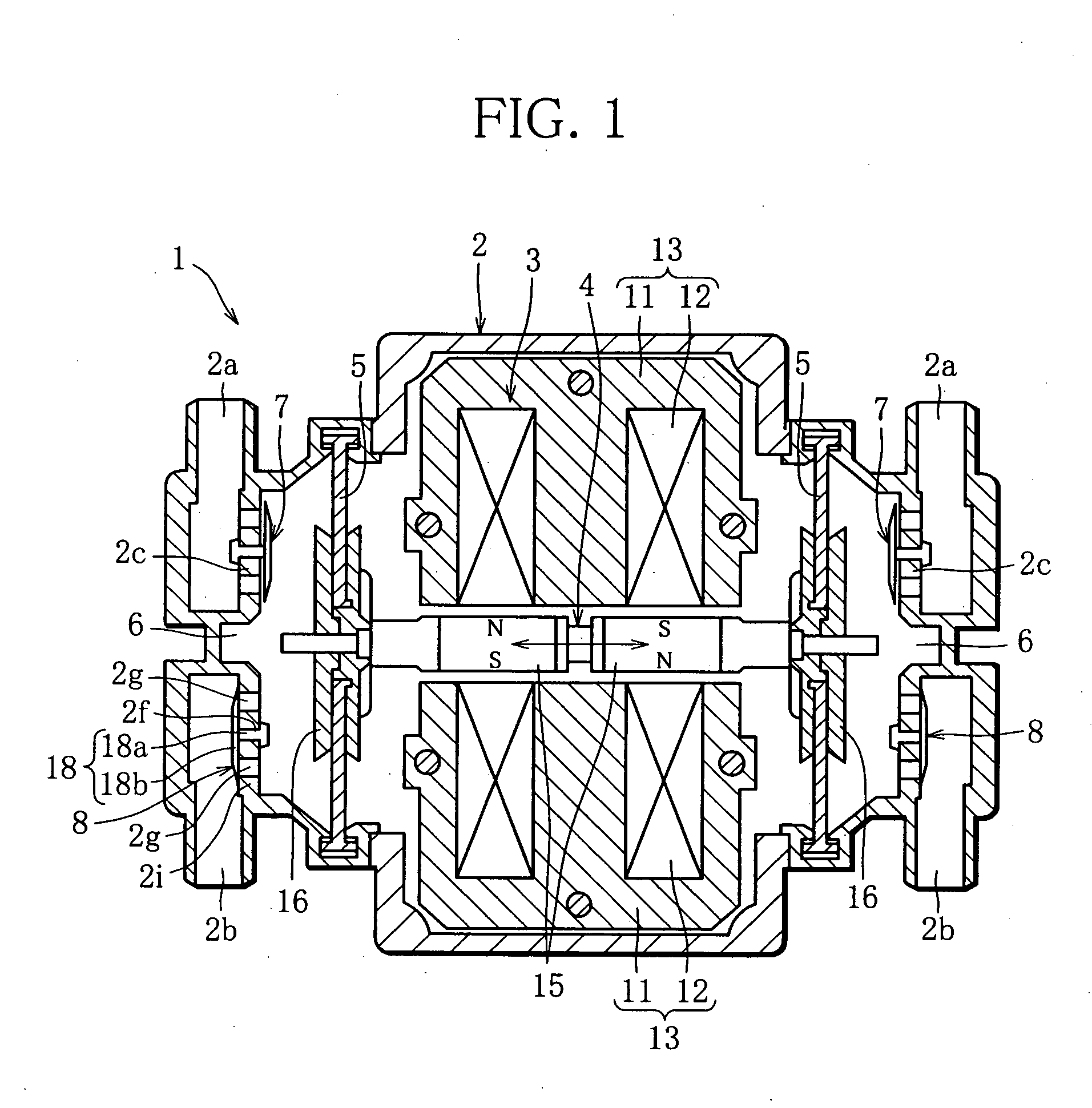
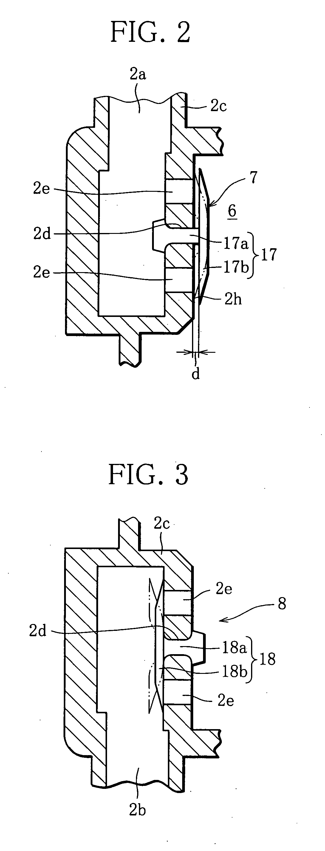
[0025] Each casing 2c has a suction port 2a and a discharge port 2b each connec...


PUM


Abstract

A diaphragm pump comprising a pressure chamber arranged such that the volume of the pressure chamber is expanded and contracted by oscillation of a diaphragm (5), a suction-side check valve (7) for sucking air into the pressure chamber and a discharge-side check valve (8) for discharging air from the pressure chamber. The suction-side check valve is arranged to close by a valve body (17) being elastically deformed and brought into close contact with a valve seat, and open by the valve body elastically returning to the normal shape and coming out of contact with the valve seat. The discharge-side check valve is arranged to open by a valve body (18) being elastically deformed and producing a space relative to a valve seat, and close by the valve body elastically returning to the normal shape and coming into close contact with the valve seat.

Description

BACKGROUND OF THE INVENTION [0001] 1. Field of the Invention [0002] This invention relates to a diaphragm pump having a pressure chamber arranged such that the volume of the pressure chamber is expanded and contracted by oscillation of a diaphragm. [0003] 2. Description of the Related Art [0004] A diaphragm pump comprises, as a wall of a pressure chamber, a diaphragm which is driven, for example, by an electromagnet to oscillate so that the oscillation of the diaphragm expands and contracts the volume of the pressure chamber alternately. The diaphragm pump sucks a fluid (air, for example) into the pressure chamber through a suction-side check valve when the volume of the pressure chamber is expanded, and pressurizes and discharges the air from the pressure chamber through a discharge-side check valve when the volume of the pressure chamber is contracted. [0005] Generally, when the discharge pressure of the diaphragm pump is raised, the discharge quantity thereof tends to decrease. W...

Claims


Application Information

Patent Timeline
IPC IPC(8): F04B17/00
CPCF04B45/043F04B53/1065F04B45/047
Inventor ICHIYANAGI, ISAOMAEGAWA, KAZUHIKO
Owner YASUNAGA AIR PUMP
Why Eureka
Try Eureka