Orthodontic Plate and Method

a technology applied in the field of orthodontic plates and methods, can solve the problems of increasing the length of orthodontic treatment time, affecting the treatment effect, so as to achieve the effect of preventing tooth movement and preventing tooth movemen

Inactive Publication Date: 2007-11-08
OSTEOMED
View PDF8 Cites 62 Cited by
  • Summary
  • Abstract
  • Description
  • Claims
  • Application Information

AI Technical Summary

Problems solved by technology

Furthermore, a particular tooth serving as an anchor may actually move because of counter-forces caused by the tendency of the other teeth to resist movement.
However, when smaller forces are used, the length of time involved in the orthodontic treatment increases significantly.
When multiple teeth serve as an anchor, the resulting tooth-movement may be somewhat unpredictable.
However, patients typically dislike the headgear and patient compliance is often inadequate.
This compromises the orthodontic treatment as well as the result.
Even when patients do wear headgear, the use is typically limited to about 10-12 hours per day.
Additionally, endosseous implants are unsuitable in juveniles or adolescents, as a hole must be drilled into the alveolar portion of the jawbone.
Insertion of an endosseous implant into this area will harm unerupted teeth that are still forming.
Further, since young patients are still growing, an endosseous implant will become engulfed as vertical development of the alveolar bone continues, and the implant will progressively “sink,” becoming inaccessible and difficult to remove.
These types of anchors are rigid, thick and do not easily conform to the unique bone morphology found at the surgical site or into a desired direction.
Further, the bone-anchor interface surface may be very complex to allow and foster bone ingrowth.
Additionally the attachment procedure connecting the device to teeth is complex and often requires additional laboratory steps.
Since “closed” or “ring-type” orthodontic connectors, such as elastic bands and chains, cannot be readily attached to the closed holes, these plates provide limited directional torque and control.
This restricts treatment options, compromises outcome, and often prolongs treatment time.
Additionally, the orthodontic appliance is not as thin as the plate itself, which can cause irritation of the soft tissues.

Method used


Image

  • Orthodontic Plate and Method
  • Orthodontic Plate and Method
  • Orthodontic Plate and Method

Examples


Embodiment Construction

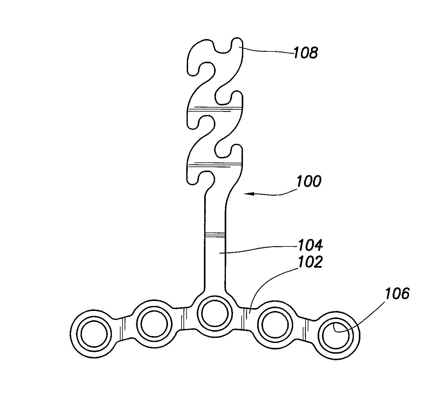
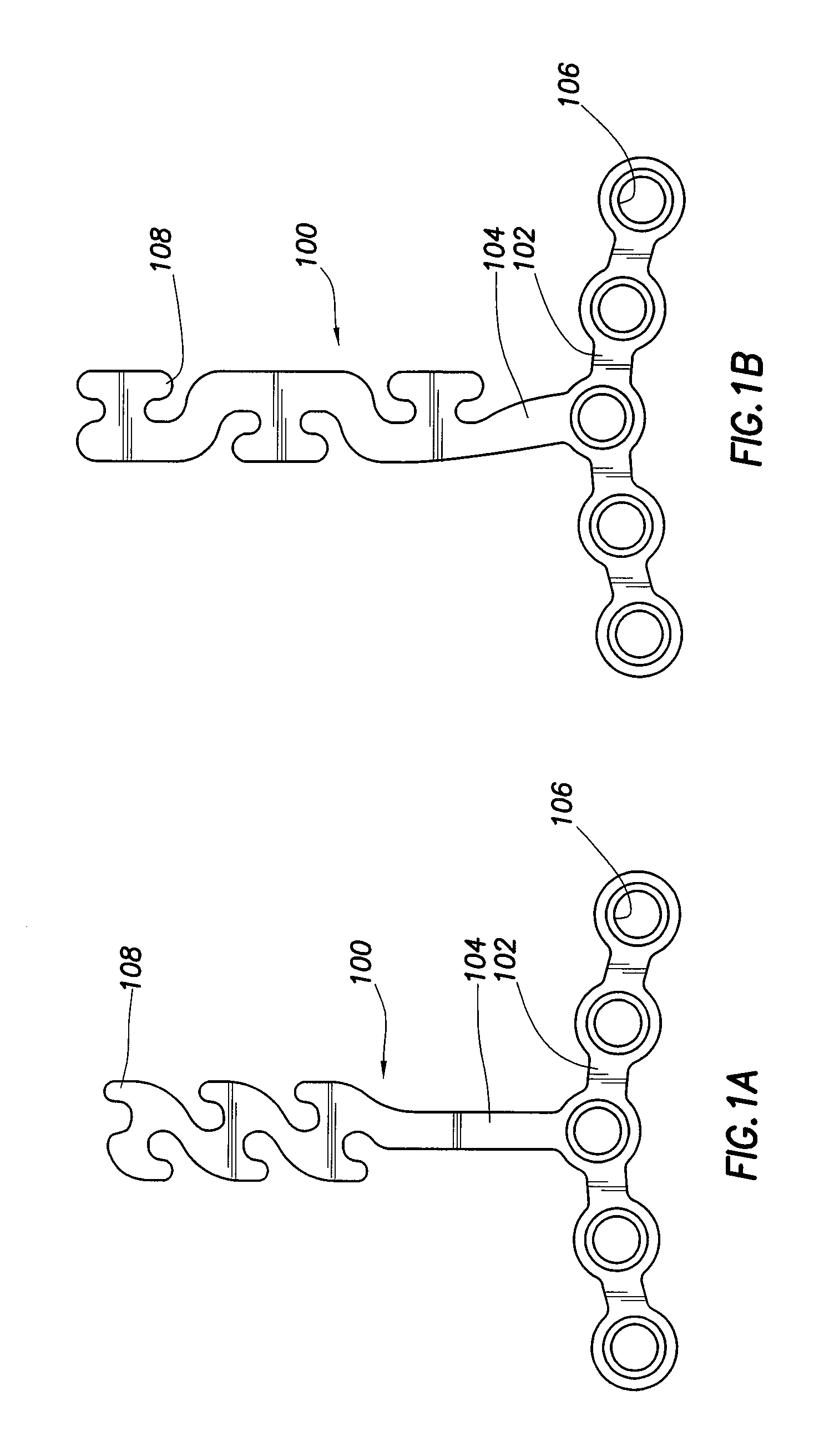
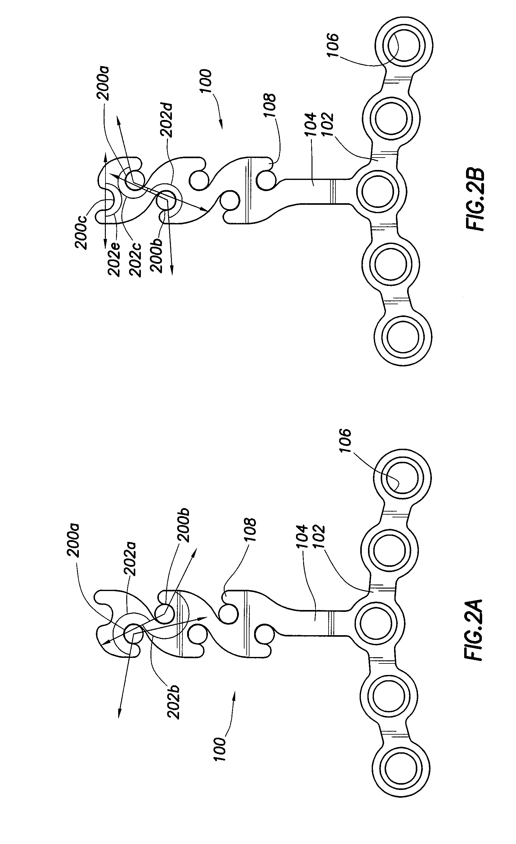
[0026] Referring now to the drawings, and in particular to FIGS. 1A and 1B, orthodontic plate 100 is shown having a bendable, malleable, substantially thin, planar construction shown in the form of a T-shaped body. Orthodontic plate 100 has a base 102, and a stem 104, which, upon installation, protrudes through the soft tissue of the gum substantially adjacent a lateral side of the dentition (shown in FIG. 5). The base 102 unitarily formed at one end of the stem 104 includes one or more holes 106 (e.g., 0.160″ diameter) extending through the base 102. The holes 106 are adapted to receive one or more fasteners 400 (shown in FIG. 4), such as flush-mounting screws. The base 102 and the stem 104 are planar, yet bendable to conform to bone contour and directionally fit a desired space. The length of the stem may vary for different applications, but may fall within the range of approximately 0.250″ to 0.450″.

[0027] The fasteners 400 situated within the holes 106 anchor the base 102 again...


PUM


Abstract

An orthodontic plate for use as a temporary bone anchor in conjunction with orthodontic treatment. The orthodontic plate includes a base and a stem extending from the base. A plurality of branches extend from the stem. In accordance with a particular embodiment of the present invention, each of the branches are configured to form respective open ended recesses.

Description

TECHNICAL FIELD OF THE INVENTION [0001] The present disclosure relates generally to the field of orthodontic devices and, more particularly, to an orthodontic plate and method. BACKGROUND OF THE INVENTION [0002] In traditional tooth movement, an orthodontist places orthodontic brackets on the teeth, and connects them to one another using orthodontic archwire. The archwire, in conjunction with tension bands, guides and provides tooth-moving forces to certain teeth, using other teeth as anchors. This traditional method of tooth movement however, has several potential shortcomings. For example, in some patients, the potential anchor tooth or teeth may be missing. Furthermore, a particular tooth serving as an anchor may actually move because of counter-forces caused by the tendency of the other teeth to resist movement. [0003] Therefore, it is often desirable to move some teeth while stabilizing other teeth. Traditionally, this stabilization, or differential tooth movement, involves app...

Claims


Application Information

Patent Timeline
Patent Type & Authority Applications(United States)
IPC IPC(8): A61C3/00
CPCA61C7/00A61C8/0096A61C8/0031
Inventor RAINES, AARON T. JR.BECKENDORF, BRANDON G.
Owner OSTEOMED
Why Eureka
Try Eureka