Gingival tissue retraction device and method

a tissue retraction and gingival tissue technology, applied in the field of tissue retraction devices and methods, can solve the problems of inability to make an impression of the prepared tooth, inability to accurately enlarge the space between the gum and the base of the tooth, and inability to accurately enlarge the space necessary for taking an accurate impression, etc., to achieve the effect of enhancing the retraction of gingival tissue and ensuring the removal

Active Publication Date: 2007-11-08
CENTRIX
View PDF42 Cites 47 Cited by
  • Summary
  • Abstract
  • Description
  • Claims
  • Application Information

AI Technical Summary

Benefits of technology

[0032] This invention further contemplates that the dam having a retentive surface may be formed of a natural or synthetic porous or cellular material, e.g. a cellular, porous or grooved plastic, or a fibrous material for defining a surface capable of retaining a retraction material bonded thereto. The fibrous material may be either natural and/or synthetic, e.g. woven or pressed cotton, rayon, nylon, linen and the like, formed in the shape of a cap or sleeve which is arranged to encircle the prepared tooth or teeth. Such cap or sleeve is preferably pre-filled with a suitable moldable or impression, putty-like retraction material, that is pliable, flowable and cohesive. When the cap or sleeve pre-filled with such moldable or impression-type material is fitted onto the prepared tooth and a biting pressure is applied onto the sleeve or cap, the flowable and pliable retraction material, which ...

Problems solved by technology

Upon the removal of the cord, it frequently happens that coagulum formed to stop the bleeding or seepage of fluid is removed with the cord to result in the seepage of additional bleeding into the space.
As a result, an impression cannot be made of the prepared tooth until the additional bleeding can be controlled or stopped.
Thus, the traditional procedure for enlarging the space between the gum and the base of the tooth necessary for taking an accurate impression is tedious, time consuming and painful or extremely uncomfortable for the patient.
Also, there exists the danger that the dentist may accidentally force the cord beyond the physiologic limit of the space to create a potential periodontal pocket which can cause the tooth to be eventually lost.
The general practice of using the cord technique is relatively difficult and tedious for the dentist.
In the event that the space between the tooth and the gum that has to be retracted is very small, it becomes even more difficult for the dentist to place the cord without injuring the gum tissue and from forcing the cord beyond the physiologic limit, an...

Method used


Image

  • Gingival tissue retraction device and method
  • Gingival tissue retraction device and method
  • Gingival tissue retraction device and method

Examples


Embodiment Construction

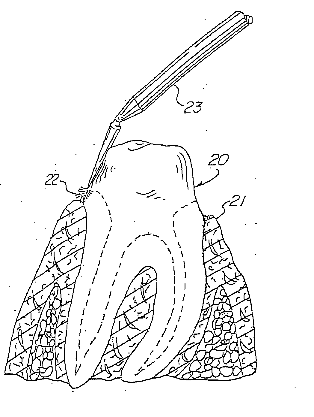
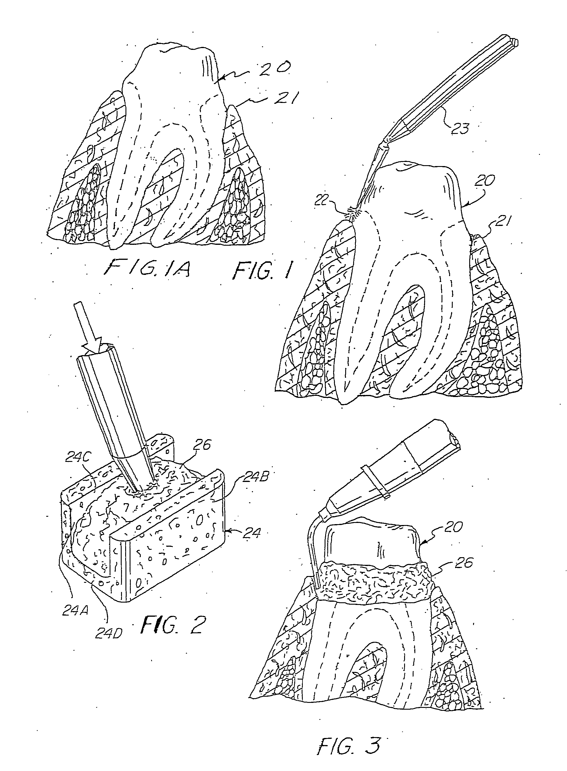
[0063] Referring to the drawings, there is shown in FIG. 1A a tooth 20 which has been prepared for receiving a crown or bridge, prior to effecting the retraction of the gingival sulcus 21. However, before the impression can be taken for preparing the crown or bridge, it is imperative that the gingival sulcus tissue 21 be retracted in order for the dentist to make an accurate impression of the prepared tooth 20.

[0064] In accordance with this invention and to control any excessive gingival bleeding, an application of a liquid hemostatic agent 22, e.g. aluminum chloride, ferric sulfate or other suitable astringent is applied to the cut tissue in the area of the gingival sulcus. The astringent can be applied with Centrix's Benda micro applicator 23 as seen in FIG. 1, or by any other suitable applicator, e.g. Centrix, Inc.'s BENDA® brush, SoftStix™ disposable applicator, or syringe, and the like. The astringent 22 is applied with moderate pressure and by rubbing the astringent solution ...


PUM


Abstract

A method and a device for effecting the cordless retraction of the gingival sulcus tissue that includes a dam shaped to be fitted onto a tooth. In one embodiment, the well of the dam is pre-filled with a predetermined amount of a flowable retraction material having a heavy viscosity or putty consistency. The preloaded tooth dam is fitted to a prepared tooth so that when pressure is applied onto the tooth dam, the retraction material is displaced under pressure and forced into the sulcus, causing the gingival tissue to retract away from the tooth to enlarge the gingival sulcus. In another embodiment the cap is filled with a dilatant material. In another embodiment, the cap is filled with an impregnated compressible porous material. In yet another embodiment, the cap is pre-dosed with an astringent or hemostatic agent.

Description

RELATED APPLICATIONS [0001] This application is a continuation in part of International application No. PCT / U.S. Ser. No. 07 / 08232 filed Mar. 30, 2007, which is a continuation in part application of U.S. application Ser. No. 11 / 398,134 filed Apr. 5, 2006, which is a continuation in part application of U.S. application Ser. No. 11 / 139,912 filed May 27, 2005, now U.S. Pat. No. 7,195,483, which is a continuation of International Application No. PCT / US2003 / 037711 with an international filing date of Nov. 25, 2003, which is a continuation in part application of U.S. application Ser. No. 10 / 307,695 filed Dec. 2, 2002, now U.S. Pat. No. 6,890,177 B2, each of which is incorporated herein by reference. [0002] This application is also a continuation-in-part application of U.S. application Ser. No. 11 / 122,870 filed May 5, 2005, now U.S. Pat. No. 7,189,075, which is a continuation of U.S. application Ser. No. 10 / 307,695 filed Dec. 2, 2002, now U.S. Pat. No. 6,890,177, which are both incorporate...

Claims


Application Information

Patent Timeline
IPC IPC(8): A61C5/14
CPCA61C9/0033A61P7/04
Inventor DRAGAN, WILLIAM B.DISCKO, JOHN J.
Owner CENTRIX
Why Eureka
Try Eureka