Multiband radio with transmitter output power optimization

a multi-band radio and output power technology, applied in the field of portable radios, can solve the problems of limiting the maximum transmitter performance achievable, limiting the output power of the transmitter, and implementing a more conservative circuit design

Active Publication Date: 2007-11-08
HARRIS GLOBAL COMM INC
View PDF17 Cites 111 Cited by
  • Summary
  • Abstract
  • Description
  • Claims
  • Application Information

AI Technical Summary

Benefits of technology

[0008] According to one aspect of the invention, the control signal is a bias control signal. In that case, the transmitter system includes a bias control circuit designed to control a bias setting for the one or more RF power transistor. The bias control circuit is responsive to the bias control signal for varying the bias setting. According to another aspect, the control signal includes a voltage control signal. In that case, the transmitter system also includes a variable power supply circuit having a variable DC voltage output coupled to one or more RF power transistors. For example, if the RF power transistor is a field effect transistor the DC voltage output would be directly or indirectly coupled to a drain of the RF power transistor. The variable power supply circuit is designed to be responsive to the voltage control signal to vary the DC voltage supplied to the RF power transistor.

Problems solved by technology

The hardware nature of this circuitry has typically resulted in certain compromises.
While this approach ensures flexibility, it is necessarily a compromise design.
For example, the transmitter output power can be limited to protect the final RF power amplifier under worst case conditions.
While necessary to protect the RF power amplifier, these fixed design parameters can limit the maximum transmitter performance achievable under certain circumstances.
However, because the RF power amplifier design must be compatible with any communication protocol, the more conservative circuit design must be implemented.

Method used


Image

  • Multiband radio with transmitter output power optimization
  • Multiband radio with transmitter output power optimization
  • Multiband radio with transmitter output power optimization

Examples


Embodiment Construction

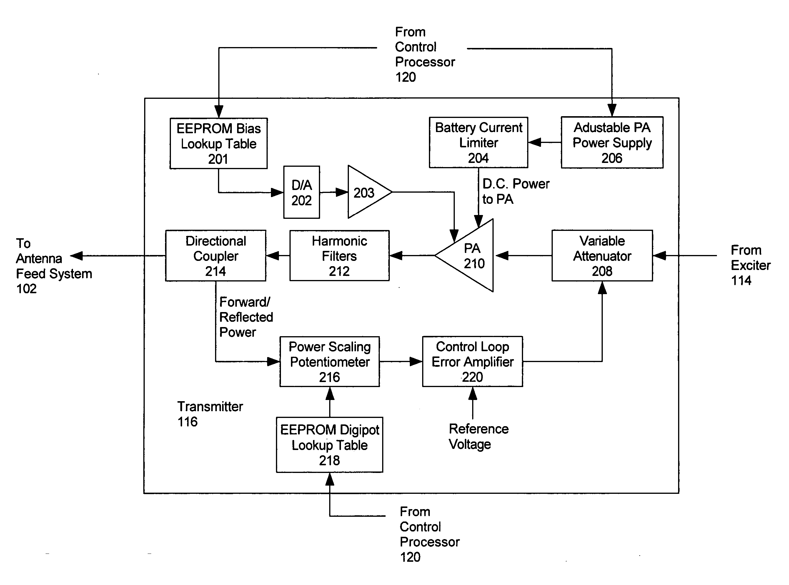
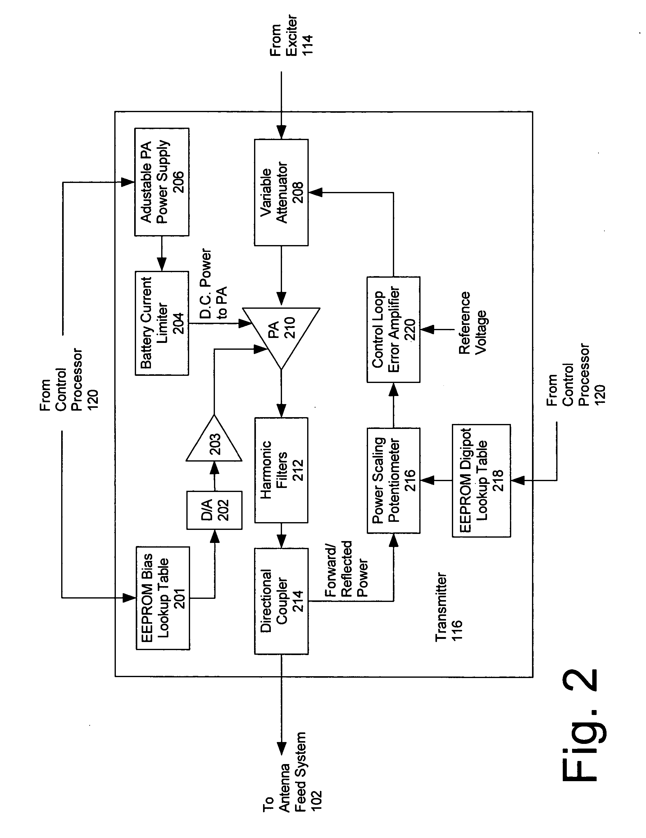
[0019] The invention concerns a radio system which includes a transmitter. The transmitter is designed to automatically reconfigure one or more circuit parameters associated with an RF power amplifier in response to certain user input commands. Specifically, a transmitter circuit configuration is automatically modified under certain conditions to produce a higher RF output power. The higher RF power output is possible because the transmitter configuration is adjusted specifically for use under a particular set of operating conditions. For example, the operating conditions can include a data rate, duty cycle, a modulation type, and / or a frequency band.

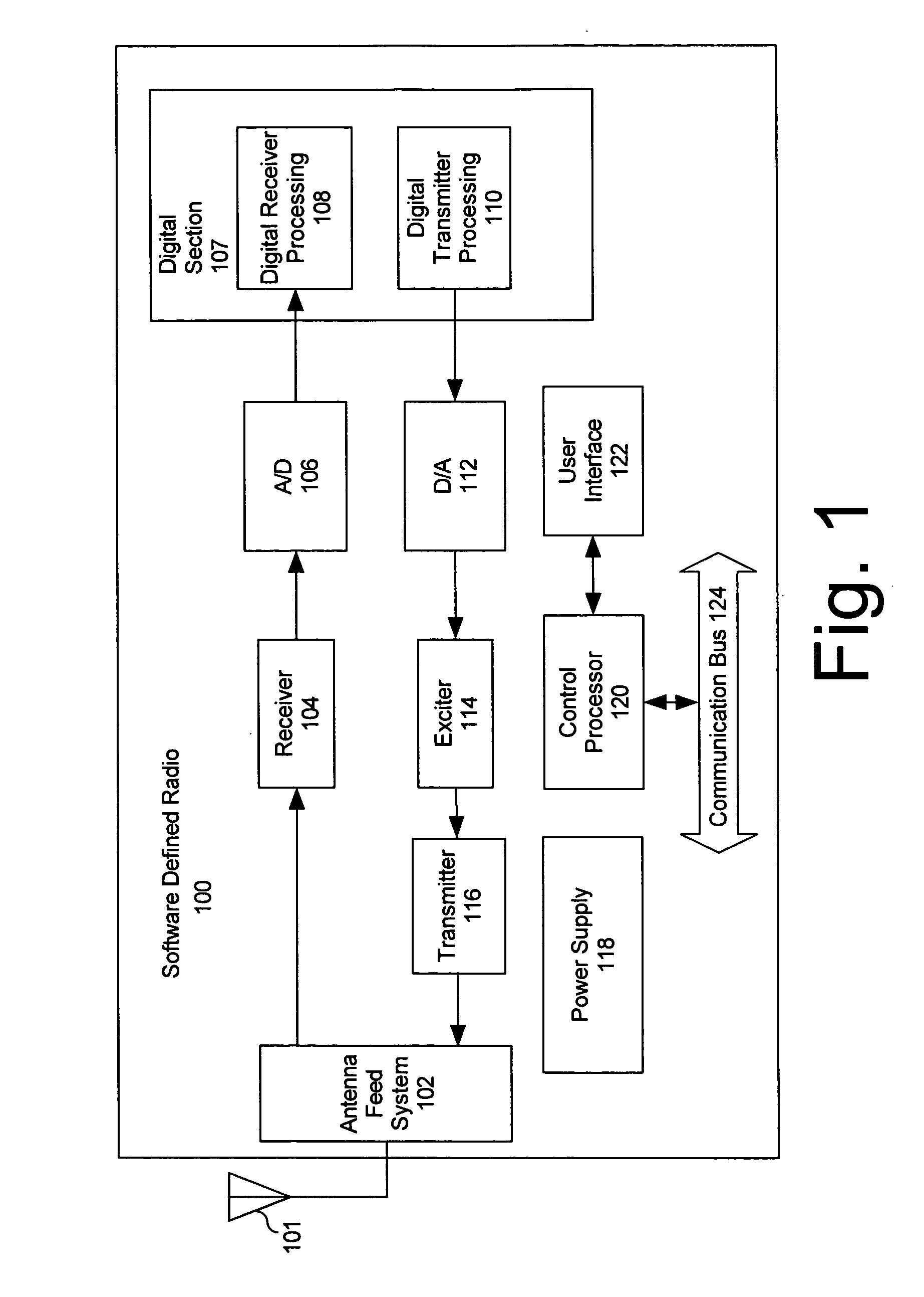
[0020] The invention can be used with a conventional radio system. However, the invention is particularly advantageous for use in connection with a software defined radio (SDR) system, which systems are well known in the art. For convenience, the invention will be described in connection with an SDR system. Still, it should be understo...


PUM


Abstract

Transmitter (116) designed to automatically reconfigure one or more circuit parameters associated with an RF power amplifier (210) in response to certain user input commands. Specifically, a transmitter circuit configuration is automatically modified under certain conditions to produce a higher RF output power. The higher RF power output is possible because the transmitter configuration is adjusted specifically for use under a particular set of operating conditions. The operating conditions that trigger the higher powered configuration include burst transmission mode.

Description

BACKGROUND OF THE INVENTION [0001] 1. Statement of the Technical Field [0002] The inventive arrangements relate to portable radios, and more particularly to maximizing transmitter power output of portable handheld radio equipment. [0003] 2. Description of the Related Art [0004] Improvements in technology have led to the development of a new generation of multi-band portable radios. These portable radios include multi-mission tactical radios that are designed to be compatible with the Joint Tactical Radio System (JTRS). The JTRS system is built upon the well known Software Communications Architecture (SCA) which establishes a system by which programmable radios can be quickly modified with software to implement any one of a wide variety of communication link protocols on a variety of frequency bands. These highly flexible radios are capable of operating over a very wide range of frequencies, for communicating voice and data using any one of a variety of modulation schemes. [0005] Not...

Claims


Application Information

Patent Timeline
Patent Type & Authority Applications(United States)
IPC IPC(8): H04B1/04H01Q11/12
CPCH04B1/406H04B1/0003H04W88/02
Inventor CARMEL, TRAVIS D.BEGHINI, KENNETH P.
Owner HARRIS GLOBAL COMM INC
Why Eureka
Try Eureka