
Universal Joint Yoke

Inactive Publication Date: 2007-11-08
JTEKT CORP +1
View PDF3 Cites 1 Cited by
  • Summary
  • Abstract
  • Description
  • Claims
  • Application Information

AI Technical Summary

Benefits of technology

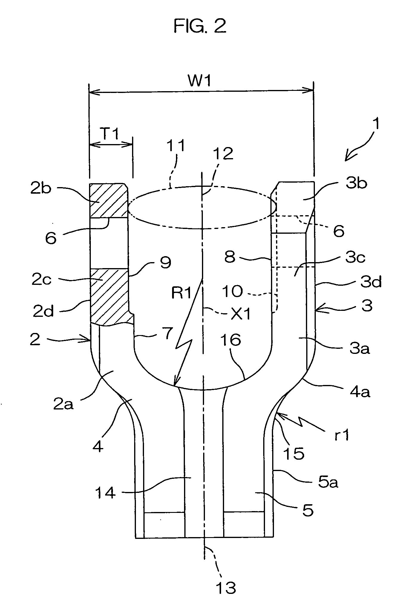
[0010] According to the present mode, the pair of tabs are formed of parallel flat plates and the relief recesses are provided only at necessary portions of the pair of tabs. Thereby, conditions that an outer width dimension between the pair of tabs should be limited to, for example, 43 mm or less for avoiding interference with peripheral components and a sufficient relief space between the tabs for inserting a joint cross therethrough should be secured can be satisfied. Moreover, while satisfying the conditions, the thickness of the tabs can be increased to, for example, 8 mm or more to secure a high strength and rigidity. Thus, it becomes possible to use a sheet metal whose thickness is 8 mm or more as a material of press molding, whereby torsional rigidity equal to that of a forged yoke can be secured.

Problems solved by technology

However, there exists a problem that the manufacturing cost is high.
However, in press yokes, although the manufacturing cost can be reduced, a problem exists that strength and rigidity are low since plate materials are used.
However, an increase in the thickness of the plate materials may cause interference with peripheral components and cracks or wrinkles during press forming, and therefore, implementation is difficult.
As a result, it has been difficult to realize high strength and high rigidity.

Method used


Image

  • Universal Joint Yoke
  • Universal Joint Yoke
  • Universal Joint Yoke

Examples


Embodiment Construction

[0017] A preferred embodiment of the present invention will be described in detail with reference to the accompanying drawings.

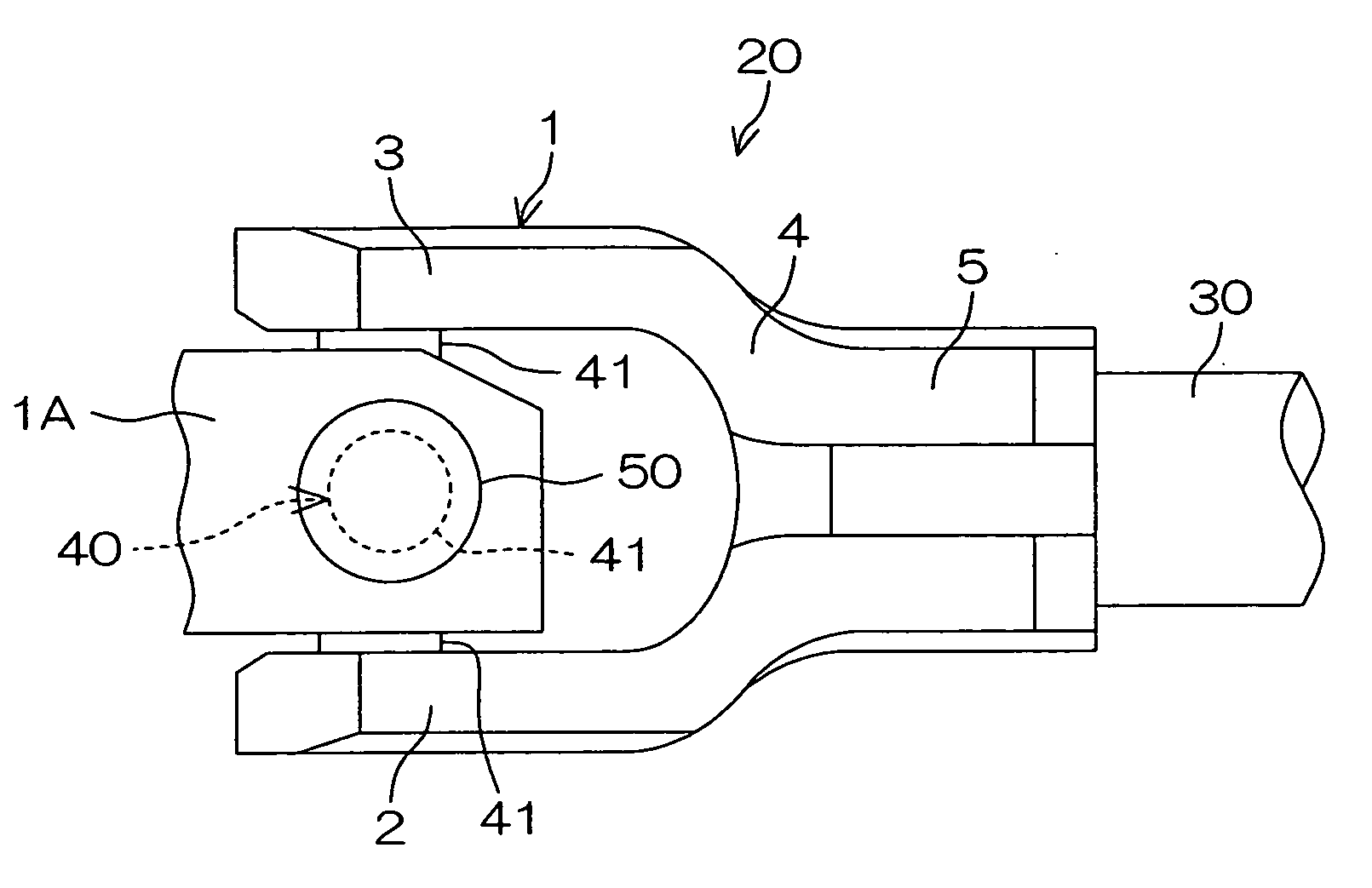
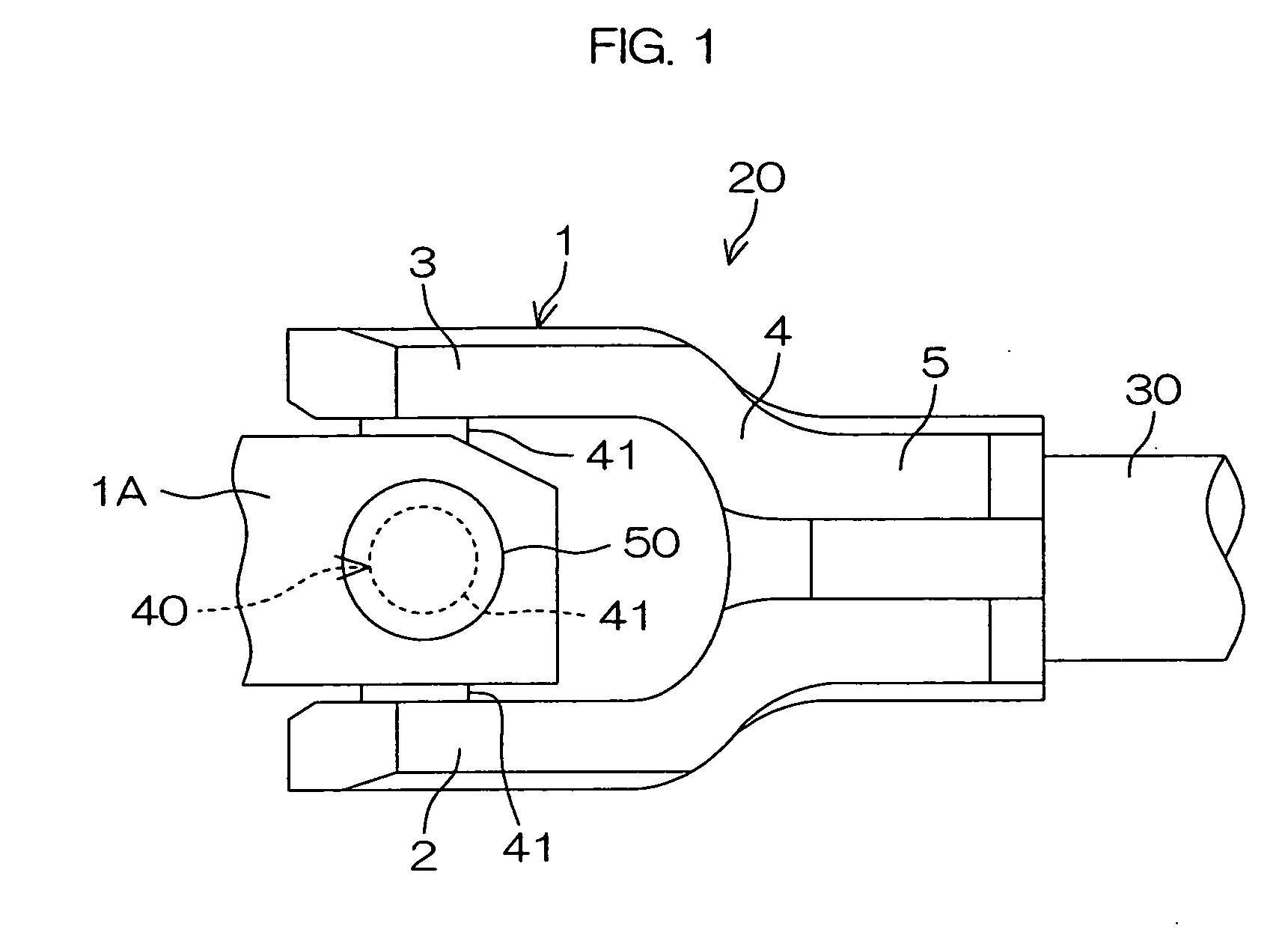
[0018]FIG. 1 is a schematic side view of a universal joint for which a yoke according to an embodiment of the present invention is used. Referring to FIG. 1, a universal joint 20 joins two shafts such as a shaft 30 formed of an intermediate shaft and a steering shaft in an automobile steering device. The universal joint 20 comprises a universal joint yoke 1, in which the shaft 30 is fitted. This yoke 1 is coupled to another yoke 1A via a joint cross 40. The another yoke 1A also has the same construction as the yoke 1 does, and respectively supports a corresponding pair trunnions 41 via bearings 50 such as needle roller bearings.

[0019] The yoke 1 is provided by press-forming as a material a sheet metal 60 as shown in FIG. 5 whose thickness S1 is 8 mm or more (S1≧8 mm). Respective portions of the press-formed yoke 1 are formed in corresponding suitable thick...


PUM


Abstract

A universal joint yoke (1) is formed by press-forming a sheet metal (60) whose thickness is 8 mm or more. The yoke (1) comprises tabs (2, 3) formed of a pair of mutually parallel flat plates. First end portions (2a, 3a) of the tabs (2, 3) are coupled to each other by a coupling portion (4). A cylindrical portion (5) to which a shaft (30) is joined extends from the coupling portion (4). From second end portions (2b, 3b) to intermediate portions (2c, 3c) of the tabs (2, 3), relief recesses (9, 10) are formed on the inside surfaces (7, 8) of the tabs (2a, 3a), respectively. By the relief recesses (9, 10), a columnar relief space (11) is defined between the tabs (2, 3). The cylindrical portion (5) includes a slit (14) extending in an axial direction of the cylindrical portion (5).

Description

BACKGROUND OF THE INVENTION [0001] 1. Field of the Invention [0002] The present invention relates to a universal joint yoke. [0003] 2. Description of Related Arts [0004] For example, in an automobile steering device, a universal joint for coupling a steering shaft and an intermediate shaft and a universal joint for coupling an intermediate shaft and a pinion shaft exist. In order to provide excellent steering stability by heightening steering rigidity, as universal joints, so-called forged yokes made of highly rigid forged moldings have been used. However, there exists a problem that the manufacturing cost is high. [0005] Therefore, using so-called press yokes made of press forming has been proposed (see Japanese Unexamined Patent Publication No.10-2339 laid open on Jan. 6, 1998 by the Japanese Patent Office, and Japanese Unexamined Patent Publication No. 2001-12490 laid open on Jan. 6, 2001 by the Japanese Patent Office, for example.) [0006] However, in press yokes, although the ma...

Claims


Application Information

Patent Timeline
IPC IPC(8): F16D3/02F16D3/26F16D3/38
CPCF16D3/387F16D3/26
Inventor KINME, SHIGETAKAKAMIKAWA, TAEUENO, MASAKOINOUE, SEIJUNIKEDA, KATSUHIKO
Owner JTEKT CORP
Learn More