DFT TECHNIQUES TO REDUCE TEST TIME AND POWER FOR SoCs

a technology of socs and test applications, applied in the field of digital integrated circuits, can solve the problems of destroying the benefits of top-level testing, wasting test time and test power, and high cost of residual scan mod

Active Publication Date: 2007-11-08
TEXAS INSTR INC
View PDF7 Cites 14 Cited by
  • Summary
  • Abstract
  • Description
  • Claims
  • Application Information

AI Technical Summary

Problems solved by technology

However, due to the presence of top-level logic (glue logic) and interaction among the cores, some top-level testing is unavoidable.
The residual scan mode is expensive in terms of test application time and test power and wipes out the benefits achieved by hierarchical scan.
This is also the case for hierarchical scan test compression; while core internal test patterns may be compressed and lead to reduction in test application time, no compression may be possible for the ful

Method used


Image

  • DFT TECHNIQUES TO REDUCE TEST TIME AND POWER FOR SoCs
  • DFT TECHNIQUES TO REDUCE TEST TIME AND POWER FOR SoCs
  • DFT TECHNIQUES TO REDUCE TEST TIME AND POWER FOR SoCs

Examples


Embodiment Construction

[0017]In the following detailed description of the embodiments of the present subject matter, reference is made to the accompanying drawings that form a part hereof, and in which are shown by way of illustration specific embodiments in which the present subject matter may be practiced. These embodiments are described in sufficient detail to enable those skilled in the art to practice the present subject matter, and it is to be understood that other embodiments may be utilized and that changes may be made without departing from the scope of the present present subject matter. The following detailed description is, therefore, not to be taken in a limiting sense, and the scope of the present present subject matter is defined only by the appended claims.

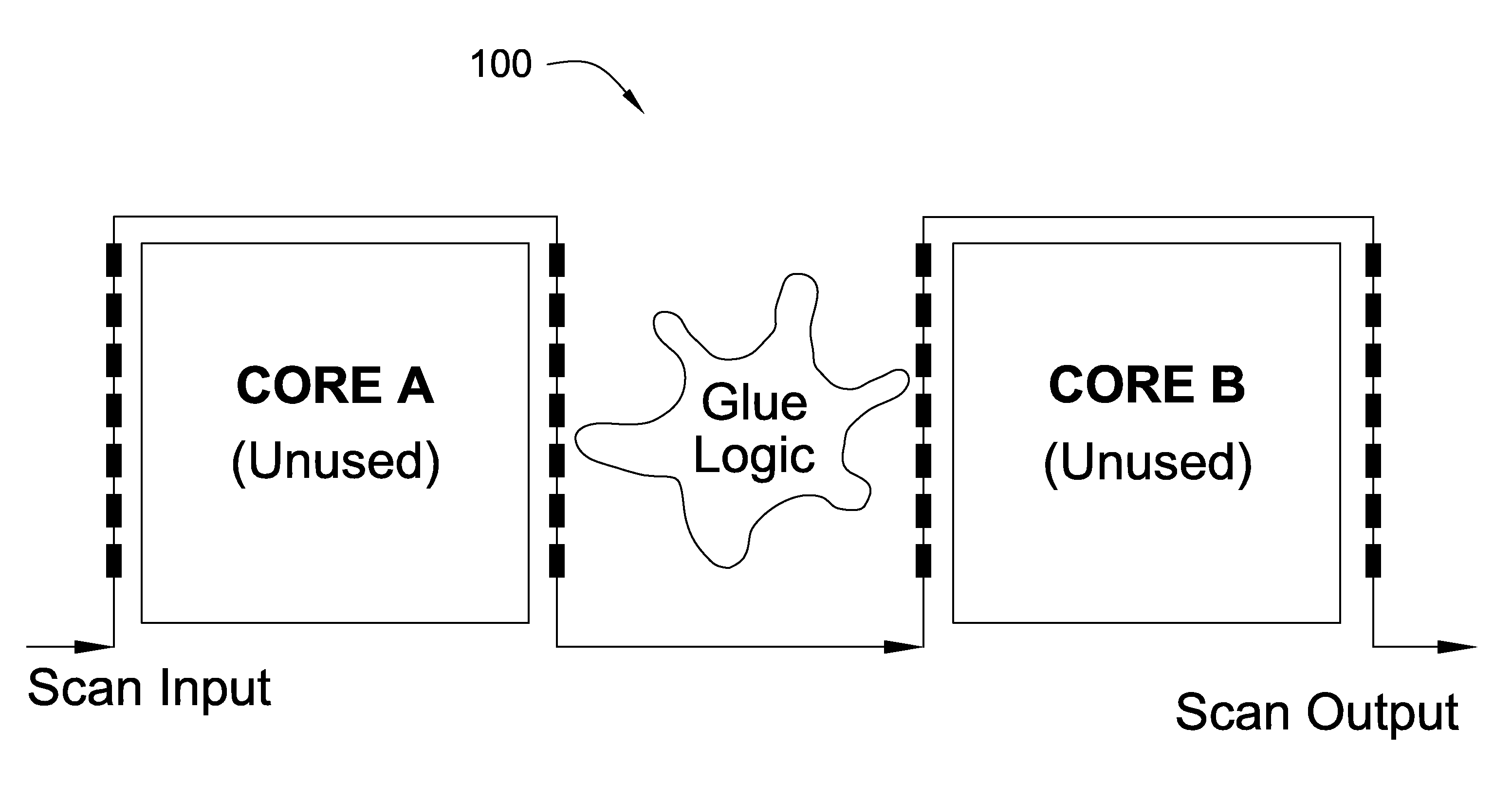
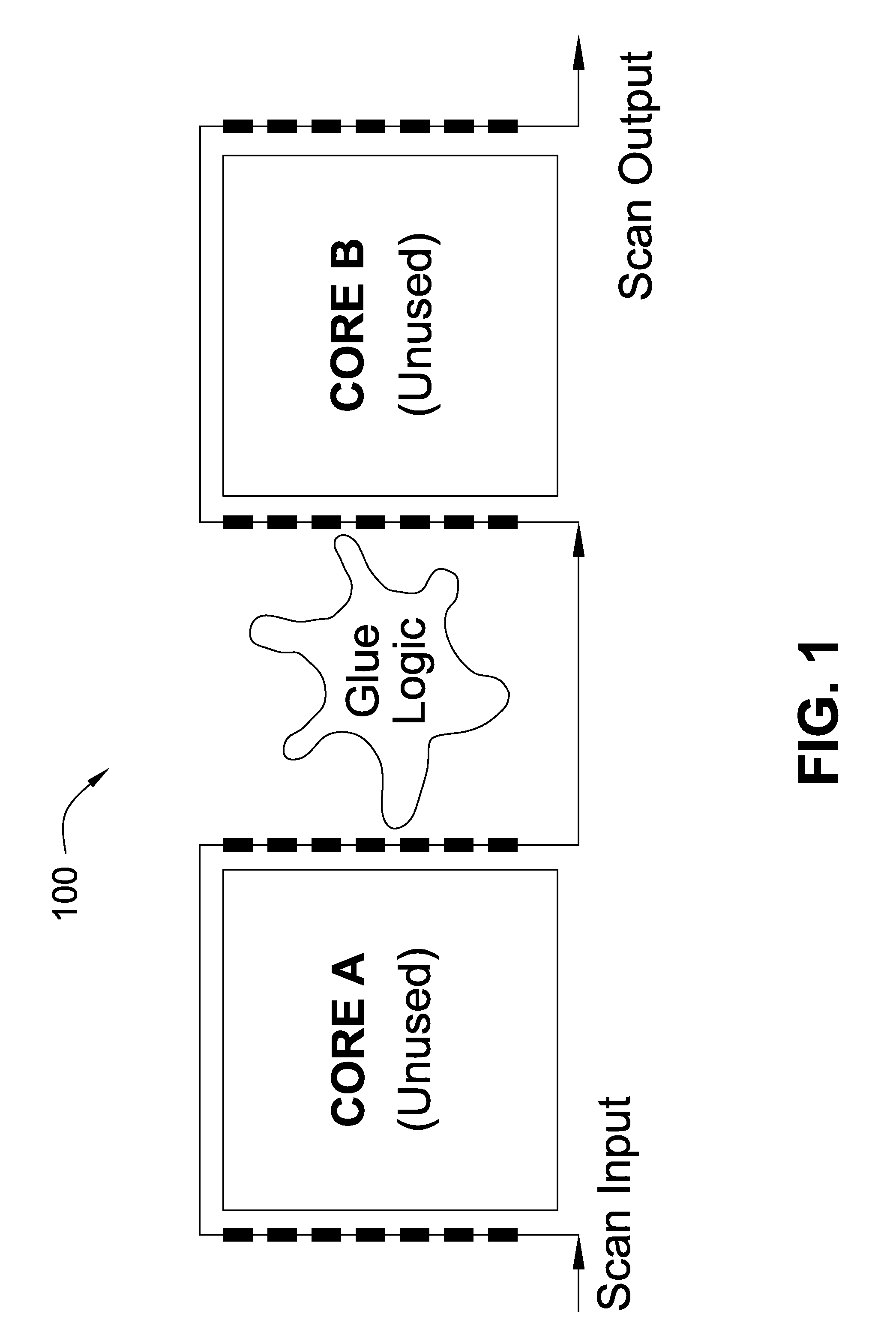
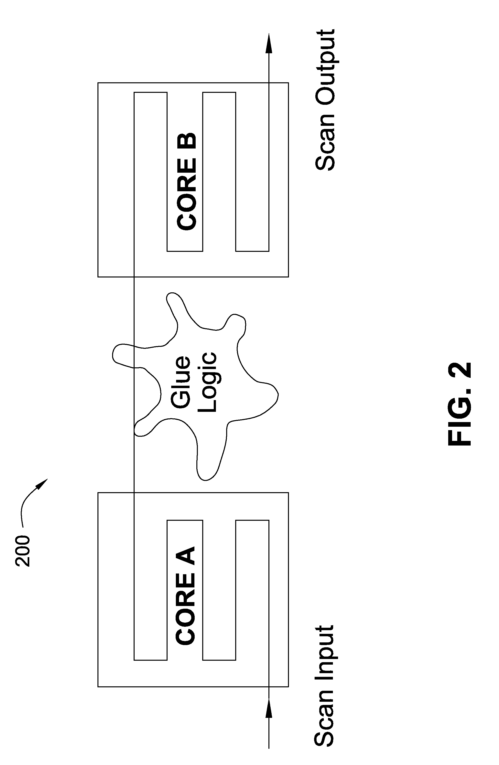
[0018]As SoCs are becoming increasingly complex, hierarchical solutions such as DFT are suited for integration of the cores. In hierarchical scan design architecture such as divide-and-conquer scan, testing is done in two phases. In the ...


PUM


Abstract

A technique for reducing the overhead of daisy chain test mode in divide-and-conquer testing using intermediate test modes that do not span all cores or all flip-flops in the core. The partial residual test mode spans across a subset of the cores and allows to bound the number of cores that a full residual test mode may span across. The interaction of the cores among one another at the top-level is analyzed and the minimum number of flip-flops in a core that must participate in a intermediate test mode is selected. Algorithms are devised to analyze the interactions among the cores and build data structures which are used for identifying intermediate test modes. Using a reconfigurable scan segment architecture, intermediate test modes are implemented that are designed to work with all known test compression solutions. Since the length of the longest scan chain in an intermediate residual test mode is much smaller than the length of the longest scan chain in the full residual test mode, there is a substantial improvement in test application time as well as test peak power.

Description

PRIORITY FROM RELATED APPLICATIONS[0001]This application claims priority under 35 USC § 119 (e) (1) of provisional application No. 60 / 745,117, filed on Apr. 19, 2006.TECHNICAL FIELD OF THE INVENTION[0002]The present invention relates generally to digital integrated circuits, and more particularly relates to Design-for-Test (DFT) techniques for Systems-on-Chips (SoCs).BACKGROUND OF THE INVENTION[0003]Sequential scan techniques are often used to test integrated circuits. According to a typical sequential scan technique, integrated circuits are designed to operate in functional mode or test mode. In functional mode, elements in the integrated circuit are connected according to a desired design and to provide a desired utility for which the integrated circuit is primarily designed. In test mode, the integrated circuit is generally designed to connect various memory elements (contained in the integrated circuit) such as flip-flops in a sequence referred to as a “scan chain” (i.e., the ou...

Claims


Application Information

Patent Timeline
IPC IPC(8): G01R31/28
CPCG01R31/318575
Inventor DEVANATHAN, V. R.RAVIKUMAR, C. P.
Owner TEXAS INSTR INC
Why Eureka
Try Eureka