Axle mechanism capable of adjusting an elevation

a technology of adjusting mechanism and adjusting mechanism, which is applied in the direction of machine supports, building scaffolds, other domestic objects, etc., can solve the problems of increasing the difficulty of assembling process, inability to provide the function of elevating or moving a flat panel display, and inevitability of losses and damages

Active Publication Date: 2007-11-15
JARLLYTEC CO LTD
View PDF11 Cites 22 Cited by
  • Summary
  • Abstract
  • Description
  • Claims
  • Application Information

AI Technical Summary

Benefits of technology

[0014]A further objective of the present invention is to provide an axle mechanism capable of adjusting an elevation, wherein a latch ring and a connecting ring latched to the base ring are connected in series between the movable rod and the upper support stand, and the latch ring has two corresponding latch grooves, such that when a force is applied to the two upper support stands for a rotation, the two circular tenons of the connecting ring are passed through a stopping edge of the latch groove and moved along its arc edge until it is latched into another latch groove, and the two upper support stands will be parallel to the two lower support stands, Now, an external force is applied to the support member to drive it to descend, so as to shorten the distance of the two upper support stands from the two lower support stands.

Problems solved by technology

However, such method cannot provide the function of elevating a flat panel display or moving it back and forth, and thus manufacturers developed a four-linking rod structure, wherein the axle mechanism includes two parallel link rods disposed separately on both sides of the axle mechanism, and each link rod has a hinge disposed on each side for changing the distance between the two link rods to adjust the elevation, since the size of the link rod is fixed.
However, the shortcomings of the axle mechanism with four link rods resides on that there are too many pivotal connecting positions, and the transmission of moment of force is in an N-shape, and thus losses and damages are inevitable.
Since the axle mechanism with four link rods of this short has more pivotal connecting points and a complicated structure, the level of difficulty for the assembling process is increased and the manufacturing cost remains very high.
However, different manufacturers design flat panel displays and bases with different specifications, and some of the components cannot be shared.

Method used


Image

  • Axle mechanism capable of adjusting an elevation
  • Axle mechanism capable of adjusting an elevation
  • Axle mechanism capable of adjusting an elevation

Examples


Embodiment Construction

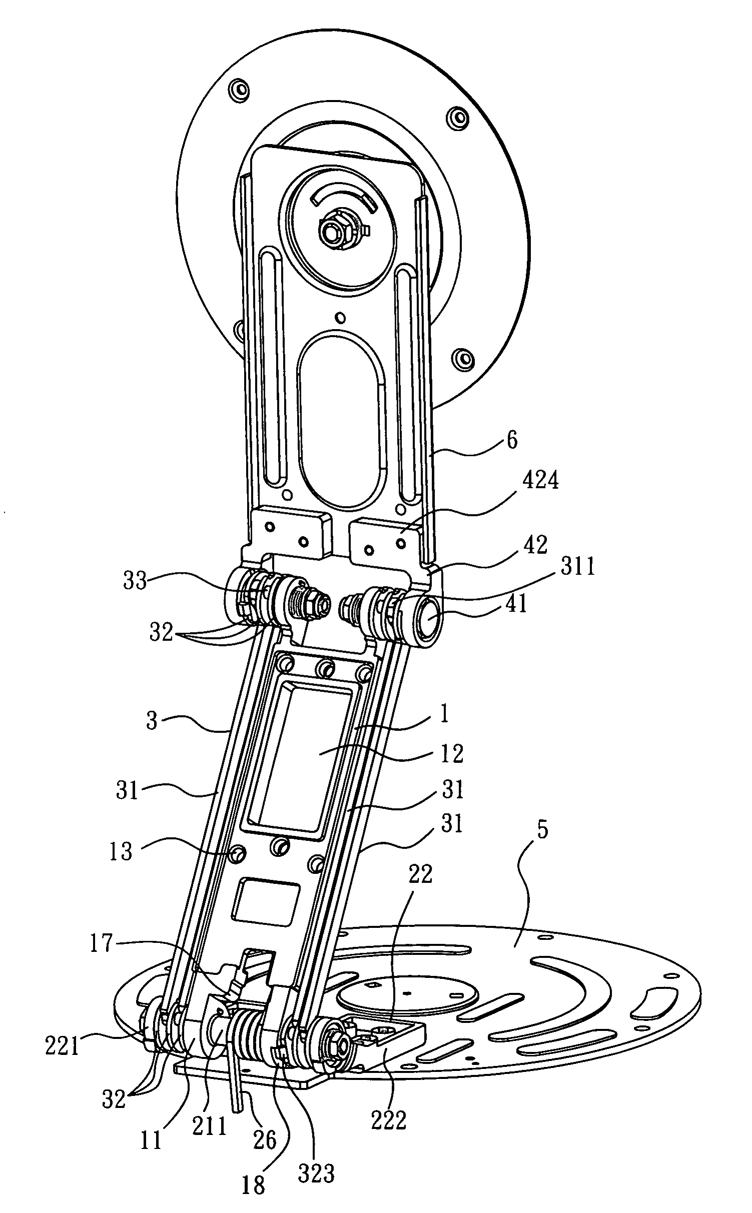
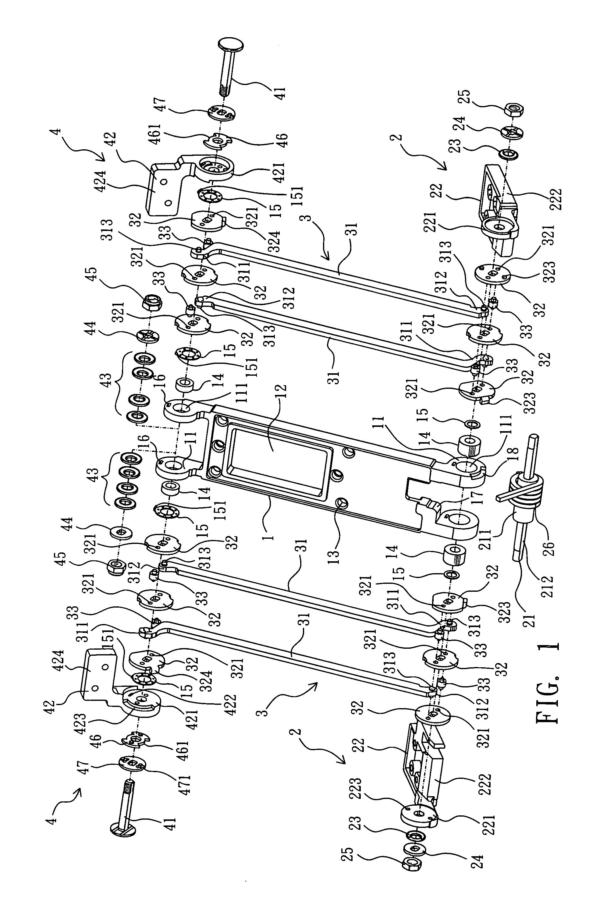
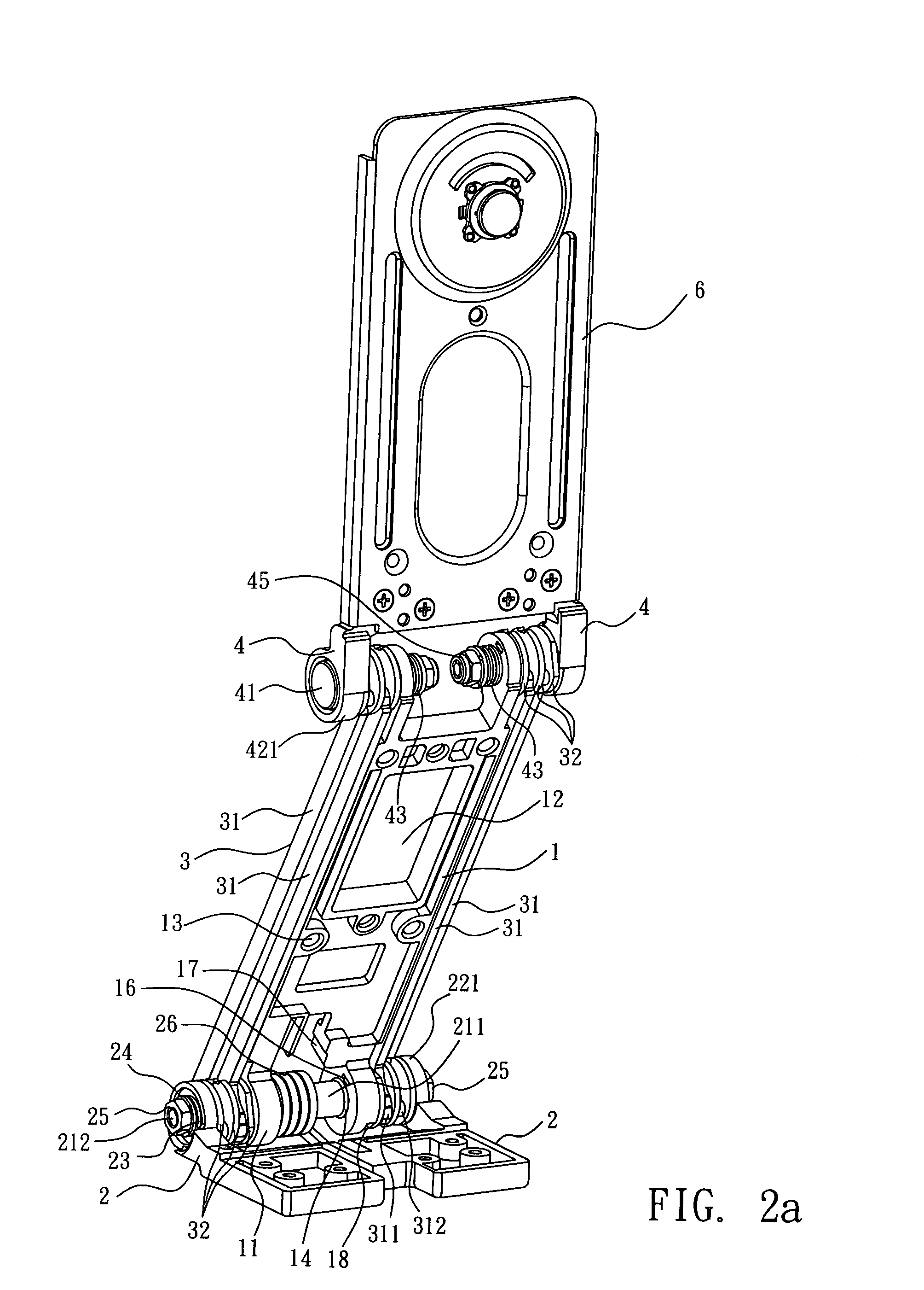
[0023]Referring to FIGS. 1 to 5, an axle mechanism of the invention comprises a support member 1, a lower hinge device 2, a dual link rod module 3, and an upper hinge device 4.

[0024]The support member 1 is a rectangular board having a board stand 11 protruded separately from the bottom and top of both left and right sides of the support member 1, and an axle hole 111 disposed thereon for connecting a lower hinge device 2 and an upper hinge device 4 as shown in the figure, and the support member 1 has a hollow groove 12 to save materials, and the surface of the board has a plurality of connecting holes 13 for connecting the covering element such as an external hood and covering the components such as the support member 1 and the two hinges 2, 4. To lower the manufacturing cost, the support member 1 of the invention is made of an aluminum alloy to improve its wear-resisting effect, and each axle hole 111 is provided for receiving an axle sheathe 14 and has an internal frictional plate...


PUM


Abstract

An axle mechanism capable of adjusting an elevation includes a support member, a lower hinge device at the bottom of the support member, an upper hinge device at the top of the support member, and a dual link rod module for connecting the upper and lower hinge devices. If the support member adjusts its elevation and front and rear distance, the turning radius of the dual link rod module is used as a moving range of the support member, such that two sets of pulling plates at the top produce a pushing action and an opposite pulling action to synchronously rotate the shaft rings on both sides of the top and drive the two movable rods to rotate without changing the original angle of the two upper support stands.

Description

BACKGROUND OF THE INVENTION[0001]1. Field of the Invention[0002]The present invention relates to an axle mechanism, and more particularly to an axle mechanism with the top and bottom of a support member connected to a upper hinge device and a lower hinge device respectively, and the upper and lower hinge devices are connected by a dual link rod module for maintaining the original angle of the support member unchanged, when a user adjusts the elevation and the front and rear distance of the upper hinge device.[0003]2. Description of the Related Art[0004]As a display device such as an LCD or a plasma TV usually features light, thin and radiation free advantages, and thus such display devices gradually replace the traditional cathode ray tube (CRT) monitors. Since LCD and plasma display devices come with a restricted viewing angle, therefore at least one axle is generally installed at a base of the display device, such that the display device can have the function of adjusting the angl...

Claims


Application Information

Patent Timeline
Patent Type & Authority Applications(United States)
IPC IPC(8): F16M13/00
CPCF16M11/04F16M11/105F16M2200/044F16M11/38F16M11/2021Y10S248/917Y10S248/923
Inventor CHENG, KANG HAN
Owner JARLLYTEC CO LTD
Why Eureka
Try Eureka