Stacked piezoelectric element, manufacturing method thereof and vibration wave driving apparatus

a piezoelectric element and manufacturing method technology, applied in piezoelectric/electrostrictive/magnetostrictive devices, piezoelectric/electrostriction/magnetostriction machines, electrical devices, etc., can solve the problems of reducing the performance of the vibration wave motor, increasing the amount of capital investment, and reducing the yield of materials, so as to reduce periodic damping and improve the effect of performan

Inactive Publication Date: 2007-11-15
CANON KK
View PDF3 Cites 13 Cited by
  • Summary
  • Abstract
  • Description
  • Claims
  • Application Information

AI Technical Summary

Benefits of technology

[0018]The present invention provides a stacked piezoelectric element that can suppress periodic damping on miniaturization of a vibration wave motor and improve its performance, a manufacturing method thereof and a vibration wave driving apparatus.

Problems solved by technology

However, the conventional stacked piezoelectric element had the following problem.
Furthermore, this reduction in adhesiveness and the periodic damping cause lowering performance of the vibration wave motor.
In the case of the conventional manufacturing method, large-scaled manufacturing equipment needs for the sheet manufacturing process of manufacturing sheets from the piezoelectric material powder and the layer stacking process of pressing and stacking them, which also increases an amount of capital investment.
In addition, machining was eventually required for the piezoelectric elements manufactured from the sheets, which may cause reducing yields of the material as well and also increases the manufacturing cost.
For this reason, the cost of electrical parts such as a transformer became high.
These parts required large space as an electrical circuit portion in spite of miniaturization.

Method used


Image

  • Stacked piezoelectric element, manufacturing method thereof and vibration wave driving apparatus
  • Stacked piezoelectric element, manufacturing method thereof and vibration wave driving apparatus
  • Stacked piezoelectric element, manufacturing method thereof and vibration wave driving apparatus

Examples


Embodiment Construction

[0033]The following description of an exemplary embodiment, features and aspects of the present invention is merely illustrative in nature and is in no way intended to limit the invention, its application, or uses.

[0034]Hereunder, a detailed description will be given as to the embodiment of the present invention with reference to the drawings.

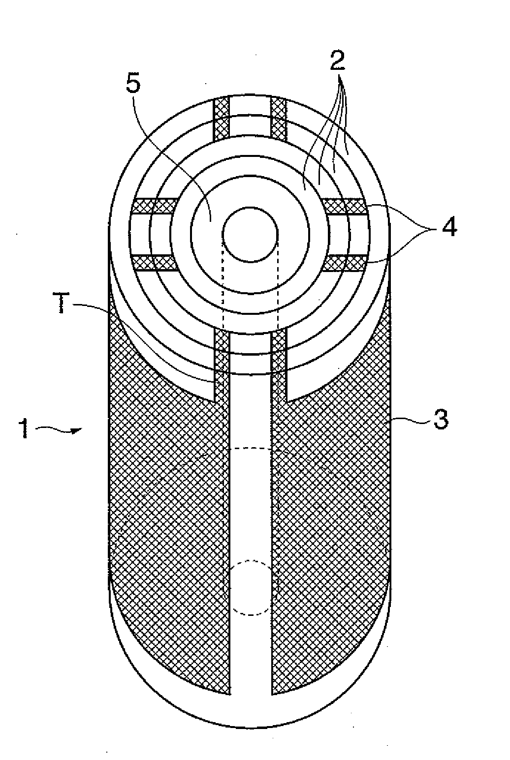
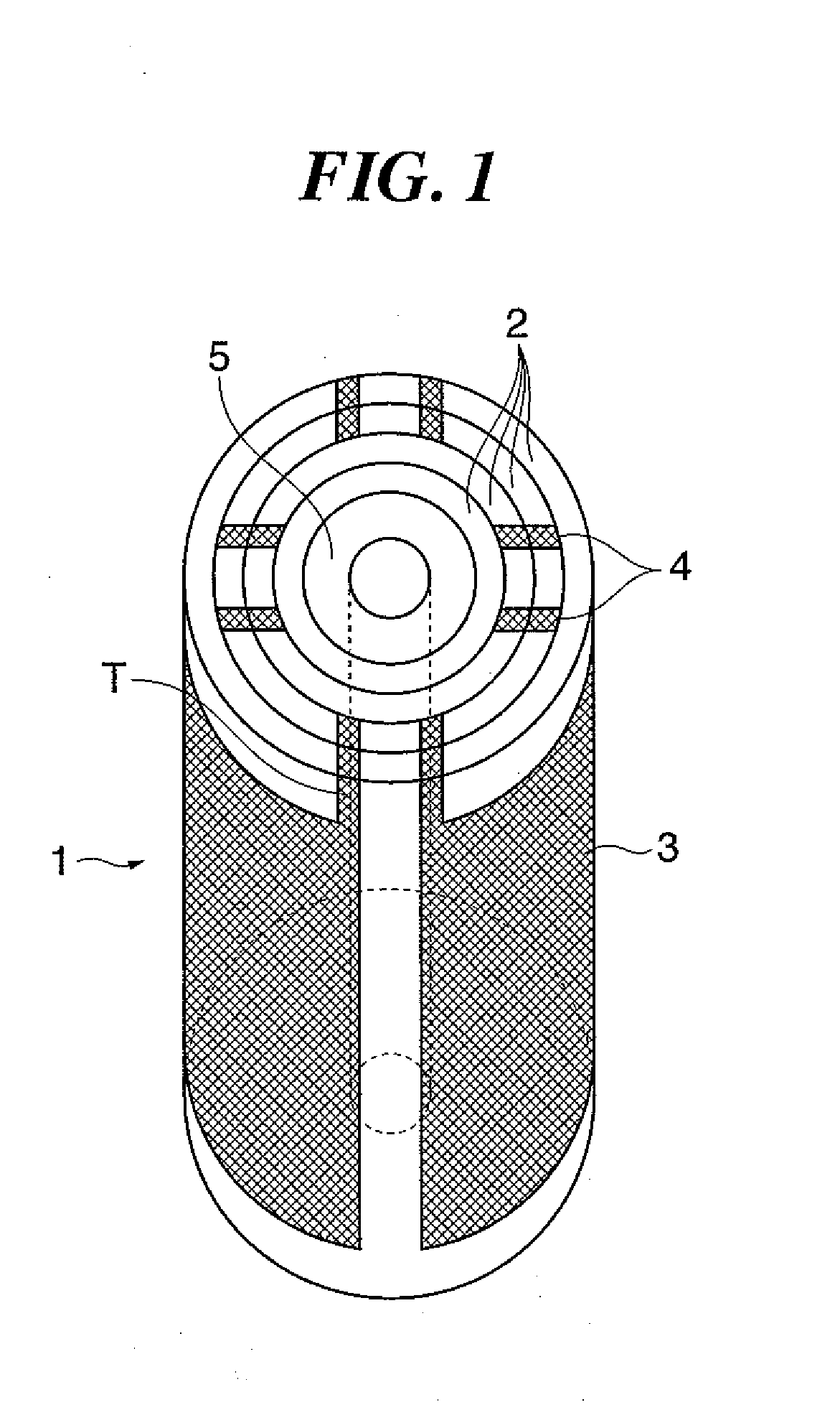
[0035]A stacked piezoelectric element according to an embodiment of the present invention is cylindrically formed and incorporated into a vibration wave motor.

[0036](Structure of the Stacked Piezoelectric Element)

[0037]FIG. 1 is a diagram showing a view of a stacked piezoelectric element according to an embodiment of the present invention. In FIG. 1, a stacked piezoelectric element 1 includes piezoelectric layers 2 composed of four layers which are concentrically (cylindrically) stacked on an outer circumference of a core 5. On an outer circumferential surface of each individual piezoelectric layer 2, an electrode layer 3 and a connection elect...


PUM

PropertyMeasurementUnit
temperatureaaaaaaaaaa
piezoelectricaaaaaaaaaa
shapeaaaaaaaaaa

Abstract

A stacked piezoelectric element comprising that can suppress periodic damping on miniaturization of a vibration wave motor and improve its performance. A stacked piezoelectric element comprises piezoelectric layers and electrode layers alternately stacked to have a shape of a cylinder. The electrode layers are divided into a plurality of electrode layer regions along a circumferential surface of the shape of a cylinder.

Description

BACKGROUND OF THE INVENTION[0001]1. Field of the Invention[0002]The present invention relates to a stacked piezoelectric element in which a piezoelectric layer and an electrode layer are stacked, a manufacturing method thereof and a vibration wave driving apparatus.[0003]2. Description of the Related Art[0004]Conventionally, piezoelectric material is a typical material that has electromechanical energy conversion functions, and is used as piezoelectric elements in various applications. Recently, stacked piezoelectric elements in which plurality of layers are stacked, integrally formed and sintered are commonly used.[0005]For instance, Japanese Laid-Open Patent Publication (Kokai) No. 6-77550, Japanese Laid-Open Patent Publication (Kokai) No. 6-120580 and Japanese Laid-Open Patent Publication (Kokai) No. 8-213664 disclose a configuration in which the stacked piezoelectric element is used for a vibration wave motor as a vibration wave driving apparatus, and in particular, for a vibrat...

Claims


Application Information

Patent Timeline
Patent Type & Authority Applications(United States)
IPC IPC(8): H01L41/083H01L41/09H01L41/187H01L41/22H01L41/273H01L41/297H02N2/00
CPCH01L41/0836H01L41/273H02N2/0015Y10T29/49155Y10T29/49124Y10T29/42H02N2/106H10N30/506H10N30/053
Inventor MARUYAMA, YUTAKAOHASHI, KAISHITSUKIMOTO, TAKAYUKI
Owner CANON KK
Why Eureka
Try Eureka