Sensor network system and sensor network position specifying method

Inactive Publication Date: 2007-11-15
HITACHI LTD
View PDF6 Cites 141 Cited by
  • Summary
  • Abstract
  • Description
  • Claims
  • Application Information

AI Technical Summary

Benefits of technology

[0012] In the sensor network system, it is no longer necessary to estimate the exact distance between a base station and sensor node, which in turn makes it unnecessary to perform strict position determination of the base station. In addition, it becomes unnecessary to perform accurate time synchronization between base stations, thus avoiding the need to densely dispose the base stations. Further, it becomes unnecessary to execute complicated calculations for reducing the influence o

Problems solved by technology

Further, it becomes unnecessary to execute complicated calculati

Method used


Image

  • Sensor network system and sensor network position specifying method
  • Sensor network system and sensor network position specifying method
  • Sensor network system and sensor network position specifying method

Examples


Embodiment Construction

[0074] A principal feature of the present invention lies in that the position of a node is specifiable by use of a locator node to thereby avoid the need for complicated processing, such as strict position determination of a base station(s).

[0075] Preferred forms of this invention will be described with reference to the accompanying drawings below.

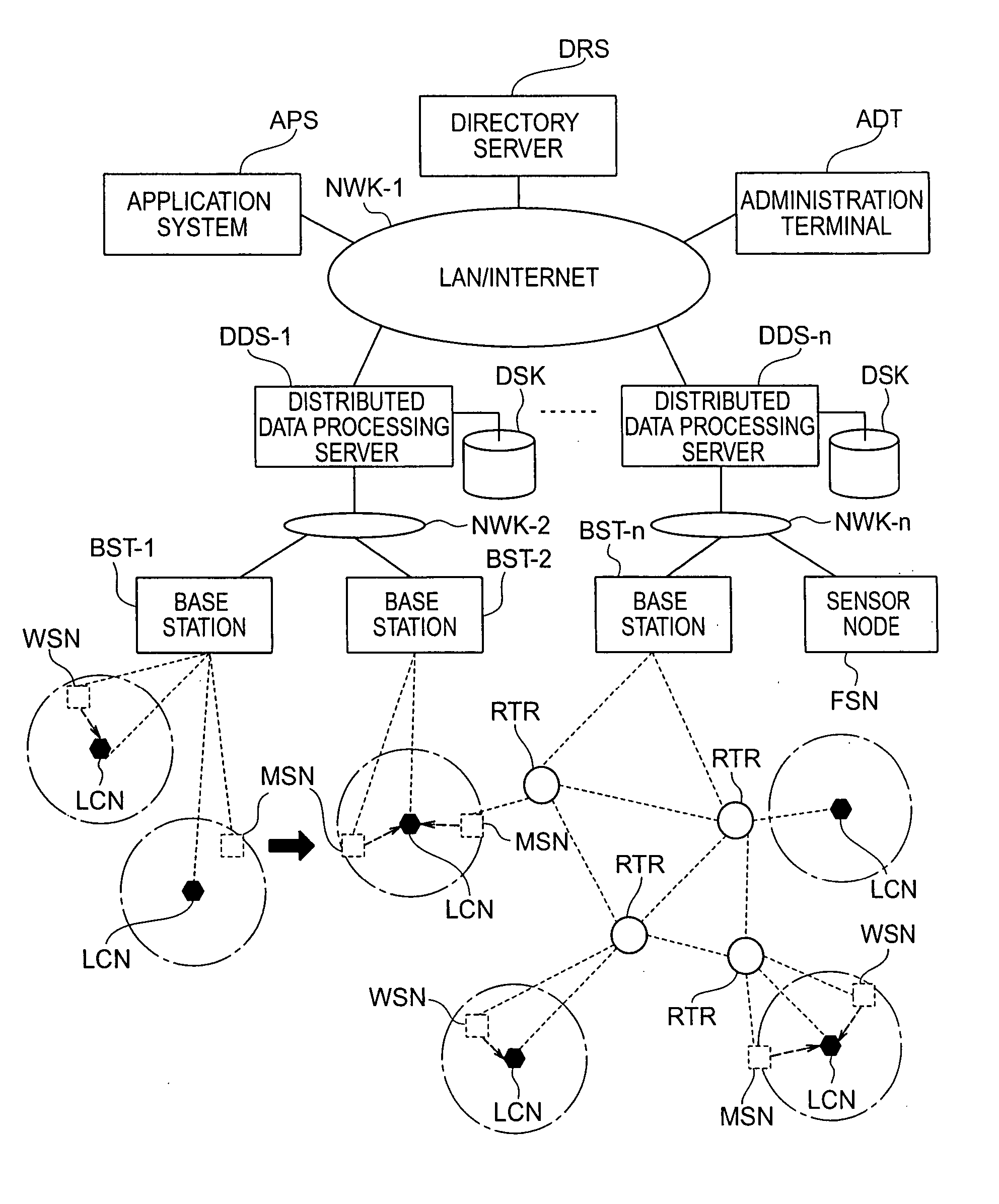
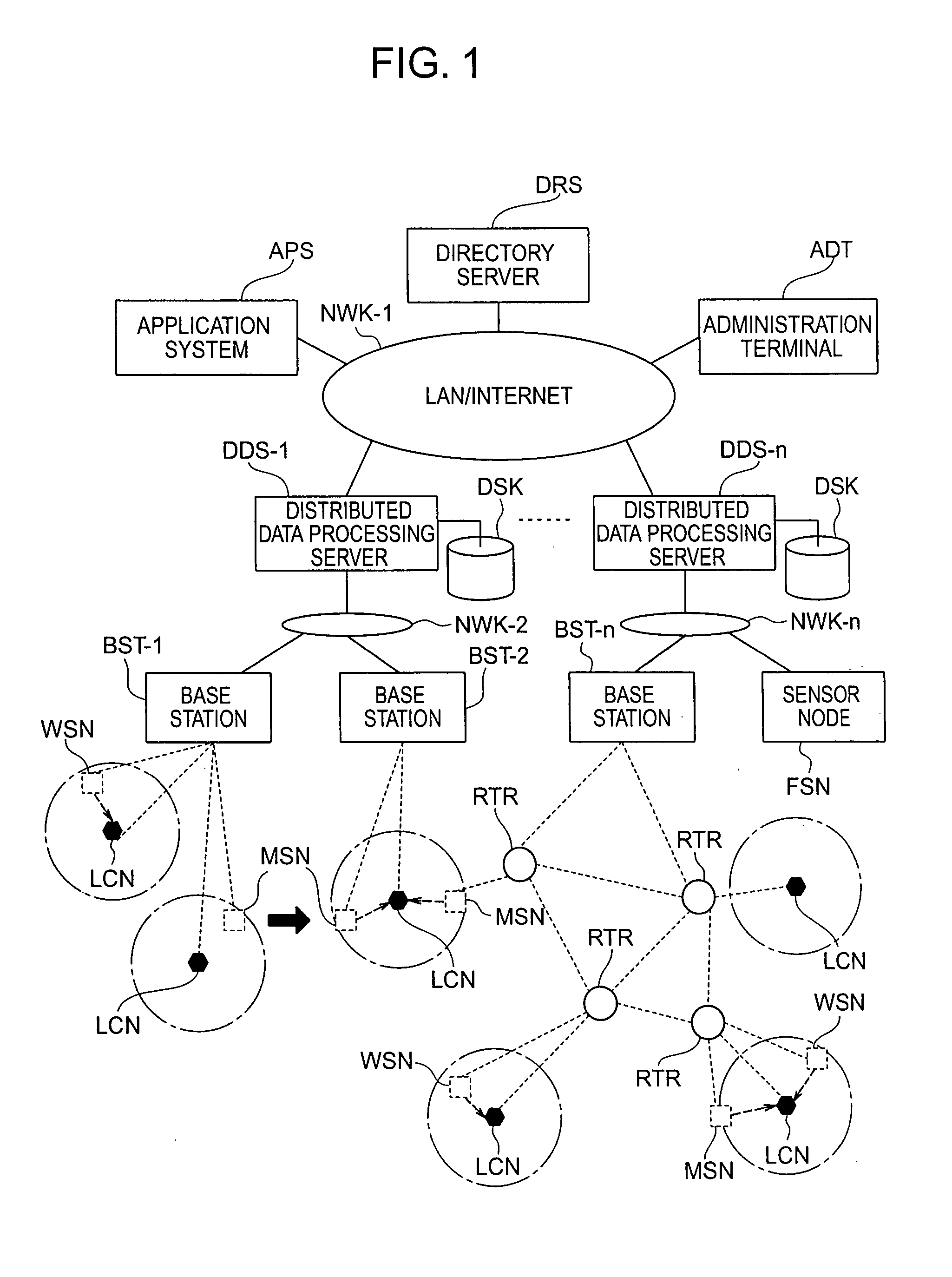
[0076]FIG. 1 is a diagram showing an overall configuration of a sensor network system embodying the invention, which is for specifying a present position of a sensor node by using a position-specifying locator node which catches or “intercepts” a communication from the sensor node. Although in the description specific components such as base stations BST, distributed data processing servers DDS and a directory server DRS are disclosed as one embodiment, it is also permissible that these functional units are integrated together in a single data processing server, which is used to execute the processing tasks required.

[0077] Several types...


PUM


Abstract

A sensor network system with its ability to specify the position of a terminal is disclosed. This system includes a locator node operative to catch a communication of a sensor node. Using this locator node, a present position of the sensor node is specified, thereby permitting services to be done based on the sensor node's position and ID information. A node position specifying method for use in the network system is also disclosed.

Description

CROSS-REFERENCE TO RELATED APPLICATION [0001] The present invention is related to U.S. patent application No. 11 / ______ (Hitachi Docket No. 310600322US01) entitled “SENSOR-NET SYSTEMS AND ITS APPLICATION SYSTEMS FOR LOCATIONING” claiming the Convention Priority based on Japanese Patent Application No. 2006-128846 filed on May 8, 2006. INCORPORATION BY REFERENCE [0002] The present application claims priority from Japanese application JP2006-128849 filed on May 8, 2006, the content of which is hereby incorporated by reference into this application.FIELD OF THE INVENTION [0003] The present invention relates generally to moving body position specifying technologies and, more particularly, to sensor network systems capable of continuously tracking changes in conditions and circumstances, such as states and positions of target objects, e.g., persons or things. BACKGROUND OF THE INVENTION Description of the Related Art [0004] Traditionally, a moving-object management method has been propos...

Claims


Application Information

Patent Timeline
IPC IPC(8): G08B1/08H04L12/28H04B7/00G08B21/00H04W64/00H04W8/02H04W60/00
CPCH04B17/27
Inventor ARITSUKA, TOSHIYUKIOHKUBO, NORIO
Owner HITACHI LTD
Why Eureka
Try Eureka