Ultra-thin digital imaging device of high resolution for mobile electronic devices and method of imaging

a mobile electronic device and ultra-thin technology, applied in the field of digital imagesensing and imagereproducing devices, can solve the problems of poor image resolution of mobile phone cameras, inconvenient use of this device as a phone, and inability to essentially improve image resolution, etc., to achieve the effect of improving the resolution of pixilated images

Inactive Publication Date: 2007-11-15
MICROALIGN TECH
View PDF6 Cites 160 Cited by
  • Summary
  • Abstract
  • Description
  • Claims
  • Application Information

AI Technical Summary

Benefits of technology

[0015] It is an object of the present invention to provide an ultra-thin and miniature digital imaging system and a method that reproduce an image of a remote object with the same quality of resolution as that of conventional megapixel photocameras. It is another object to provide an ultra-thin digital imaging camera for mobile phones that is capable of producing images comparable in quality of resolution with that of conventional digital camera photography. It is another object to provide an ultra-thin high-resolution (e.g., higher than 3 MP) digital imaging device having a dimension in the direction of the optical axis (thickness) in the order of several millimeters. It is an object of the invention to provide a digital imaging device having a dimension in the direction of the optical axis several times smaller than the dimension in the direction perpendicular to the optical axis. It is another object of the invention to provide a digital imaging device that allows compact integration with small-factor computers, Palm personal computers, iPods, smart phones, etc. It is another object is to provide a method for improving resolution of a pixilated image obtained with the use of a pixilated image sensor.

Problems solved by technology

Such networks survey a certain space, and often have to be placed in hidden locations or into locations with limited space.
However, the devices and methods of the aforementioned patent publications are aimed at improved organization of image color transfer and do not essentially improve image resolution.
Another disadvantage is that the aforementioned devices and systems require the use of a specific arrangement of color pixilation of the arrayed sensors (CMOS / CCD).
Therefore the cameras built into mobile phones have very poor image resolution.
It is understood that the use of this device as a phone is inconvenient.
This feature makes such devices inapplicable for incorporation into a mobile phone.
However, in all examples mentioned above, the weight and dimensions of existing high-resolution devices based on the use of conventional optics will conflict with the aforementioned incorporation.
Therefore, in its fundamental principles, conventional optics does not allow creation of a relatively large image of high resolution with optics having a length in the optical axis direction of about several centimeters.

Method used


Image

  • Ultra-thin digital imaging device of high resolution for mobile electronic devices and method of imaging
  • Ultra-thin digital imaging device of high resolution for mobile electronic devices and method of imaging
  • Ultra-thin digital imaging device of high resolution for mobile electronic devices and method of imaging

Examples


Embodiment Construction

Structure of the System of the Invention (FIGS. 1-6)

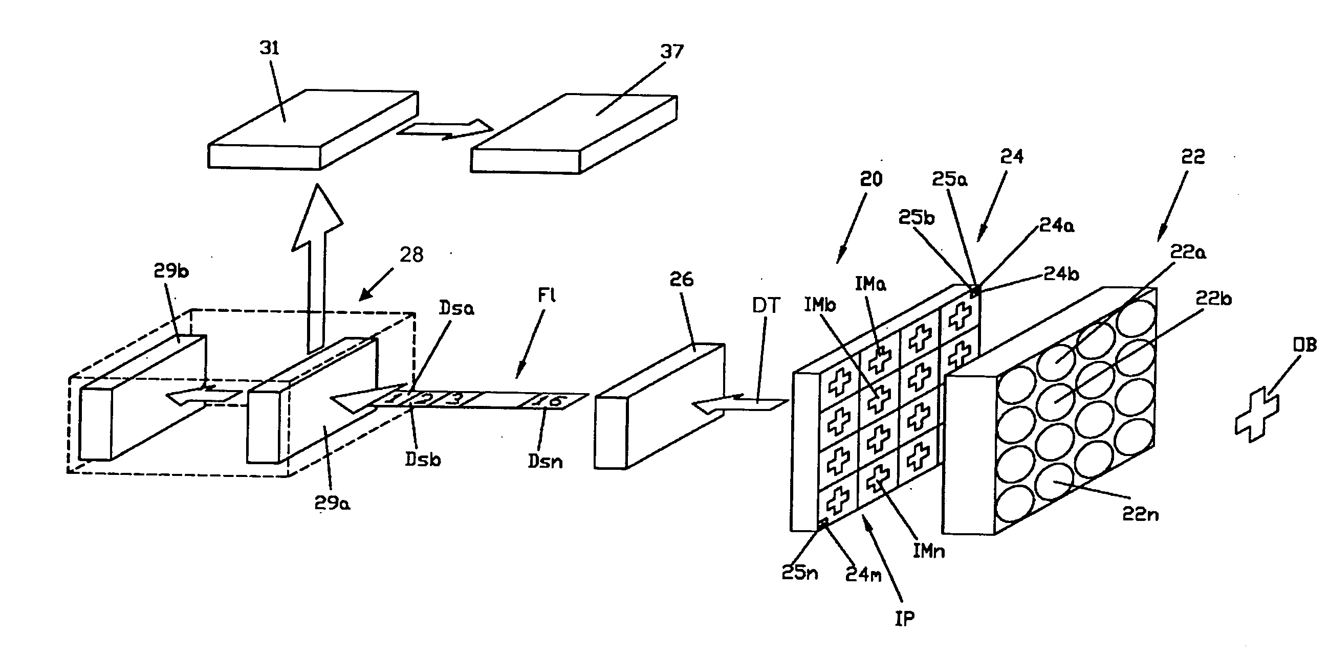
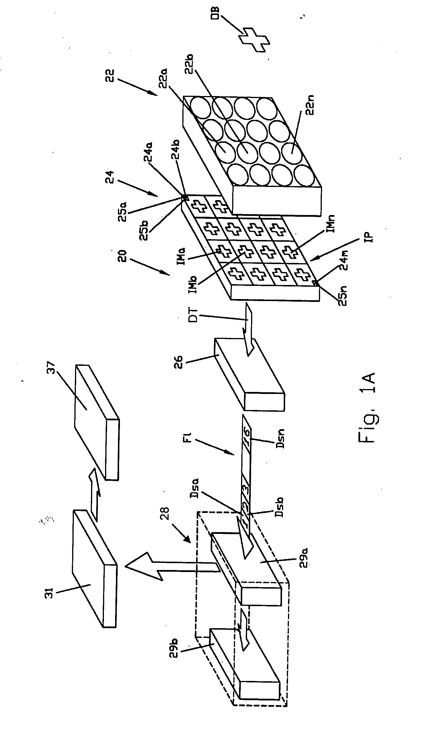
[0025] The ultra-thin digital imaging device of the invention (hereinafter referred to as device) is shown schematically in the attached drawings, where FIG. 1A is an exploded schematic three-dimensional view of the device, which, as a whole, is designated by reference numeral 20.

[0026] In the context of the present patent specification the term “ultra-thin” means that the thickness of a digital imaging device does not exceed 50% of the diagonal of the image-receiving surface in an image-receiving unit such as CCD / CMOS.

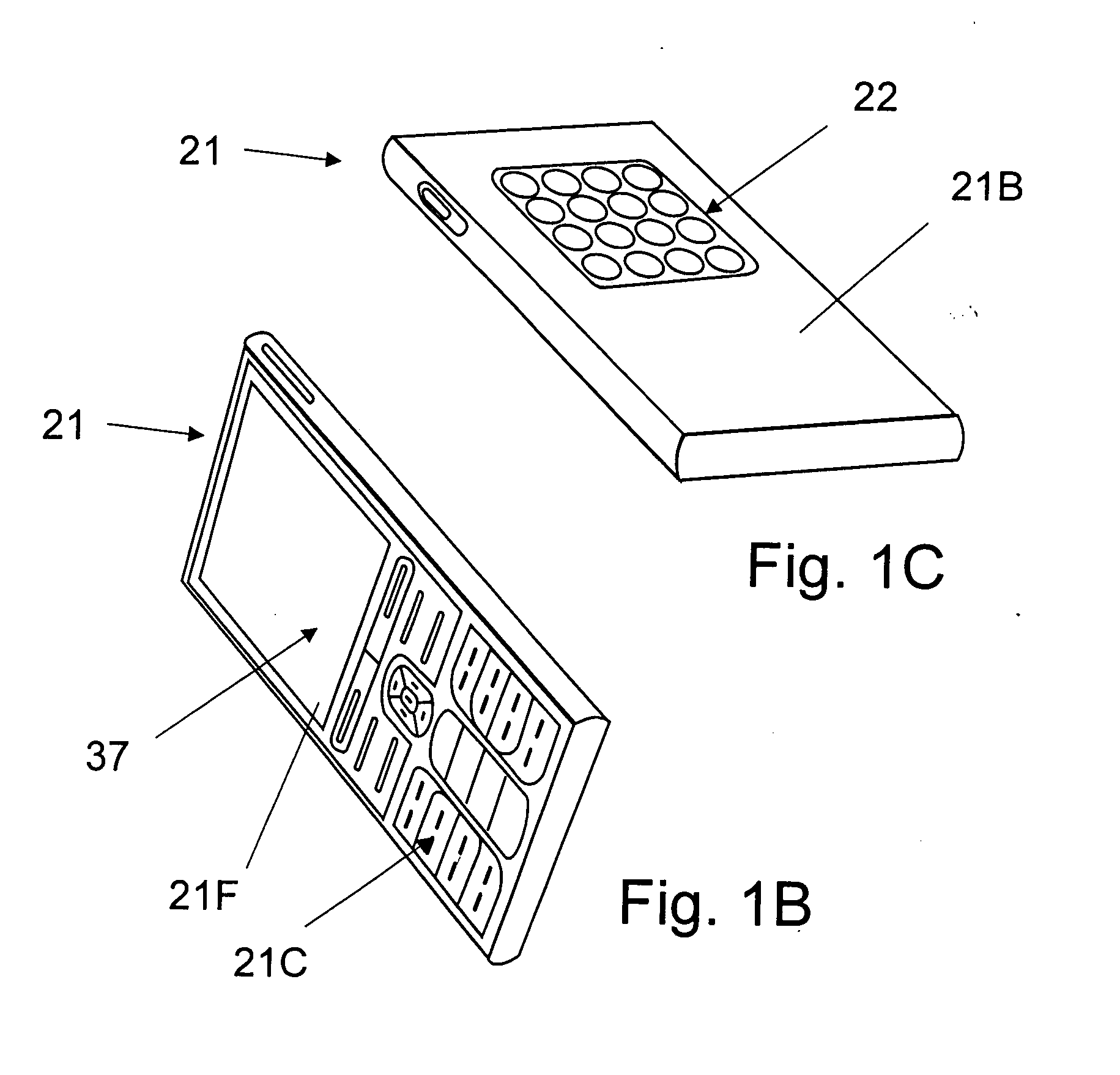
[0027] The device 20 comprises: a multi-channel imaging unit 22 that contains a plurality of optical channels 22a, 22b, . . . 22n, each in the form of a miniature objective, e.g., a microlens objective and a pixilated image sensor unit 24 with a plurality of sensing elements 24a, 24b, . . . 24m (only three of such sensing elements are shown and designated in FIG. 1A). The number “m” of the sensing elements 24a, 2...


PUM


Abstract

An ultra-thin digital imaging device has a thickness of several millimeters and is capable of producing data for creating images of 3 Mp and higher. The device comprises a multi-channel imaging unit that contains a plurality of optical channels formed by microlens objectives and a pixilated image sensor unit with a plurality of sensing elements. Each individual identical image obtained through each optical channel is pixilated and converted into electrical signals that are processed into data sets which can be stored in the imaging device and either reproduced on the display of the device or transmitted to an external image-reproducing device where the obtained data of individual images are transformed into a single, high-resolution megapixel image by means of a technique known in the art.

Description

FIELD OF THE INVENTION [0001] The invention relates to a digital image-sensing and image-reproducing device, in particular to aforementioned device for producing high-resolution megapixel images of remote objects and having dimensions in the direction of the optical axis of the device in the range of several millimeters. The digital imaging unit of the invention is most suitable for integration into devices that have limitations with regard to weight and overall dimensions, such as portable cameras and mobile electronic devices, e.g., iPods, Palm computers, smart phones, and other small form-factor mobile electronic devices and computers, miniature photo-cameras, on-board vision systems of military machines, surveillance cameras, etc. BACKGROUND OF THE INVENTION [0002] Imaging system technique is one of rapidly growing fields of industry, and the image-sensing, image-reproducing, image-reconstructing techniques find ever growing application in practice. It is worth mentioning that i...

Claims


Application Information

Patent Timeline
Patent Type & Authority Applications(United States)
IPC IPC(8): H04N5/225
CPCH04N5/2251H04N5/2253H04N5/232H04N5/2258H04N5/2254H04N23/45H04N23/54
Inventor GUREVICH, IGORFAYBISHENKO, VICTORVELIKOV, LEONID
Owner MICROALIGN TECH
Why Eureka
Try Eureka