
Network plug-and-play compliant network relay device

Inactive Publication Date: 2007-11-15
SEIKO EPSON CORP
View PDF7 Cites 20 Cited by
  • Summary
  • Abstract
  • Description
  • Claims
  • Application Information

AI Technical Summary

Benefits of technology

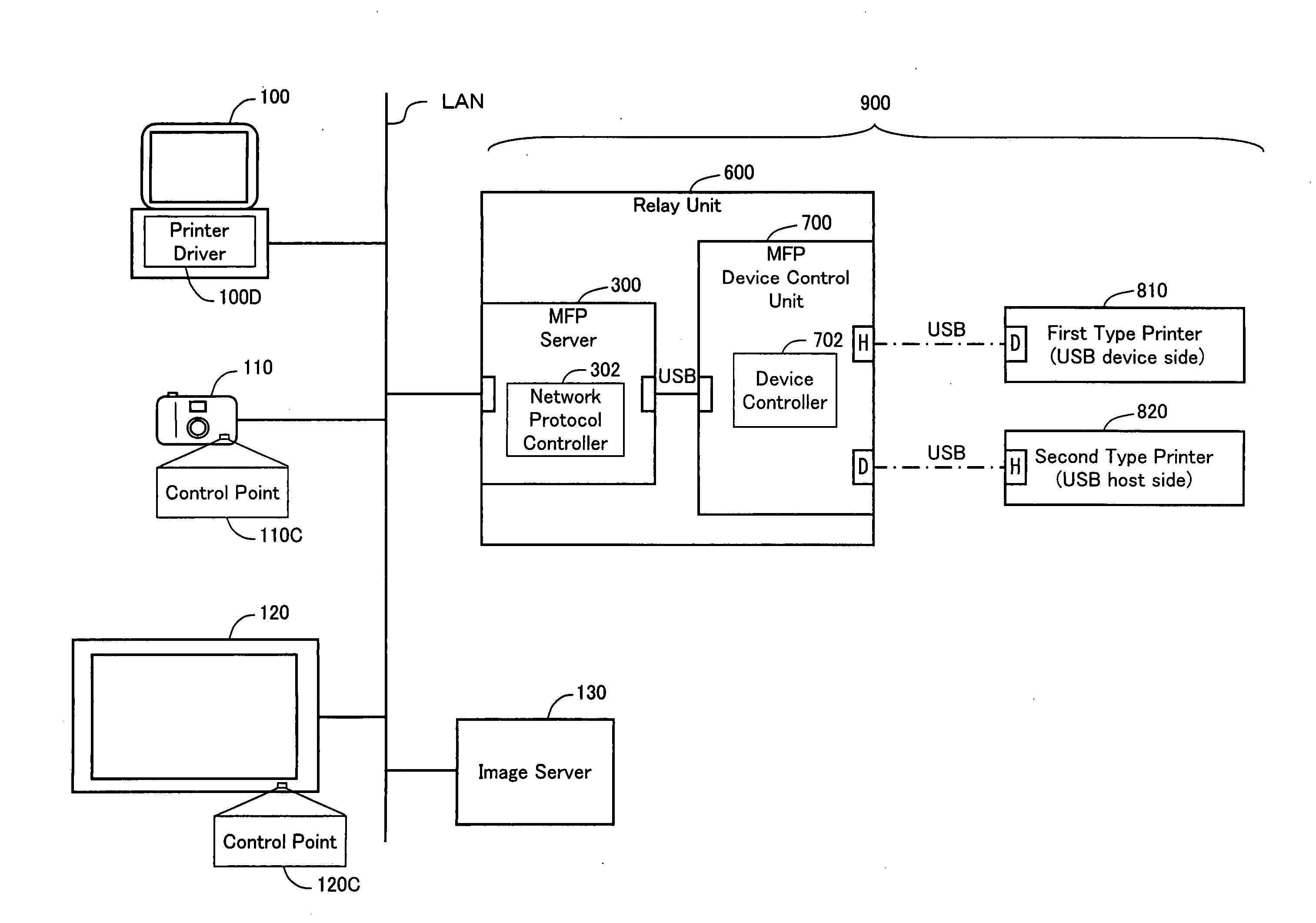
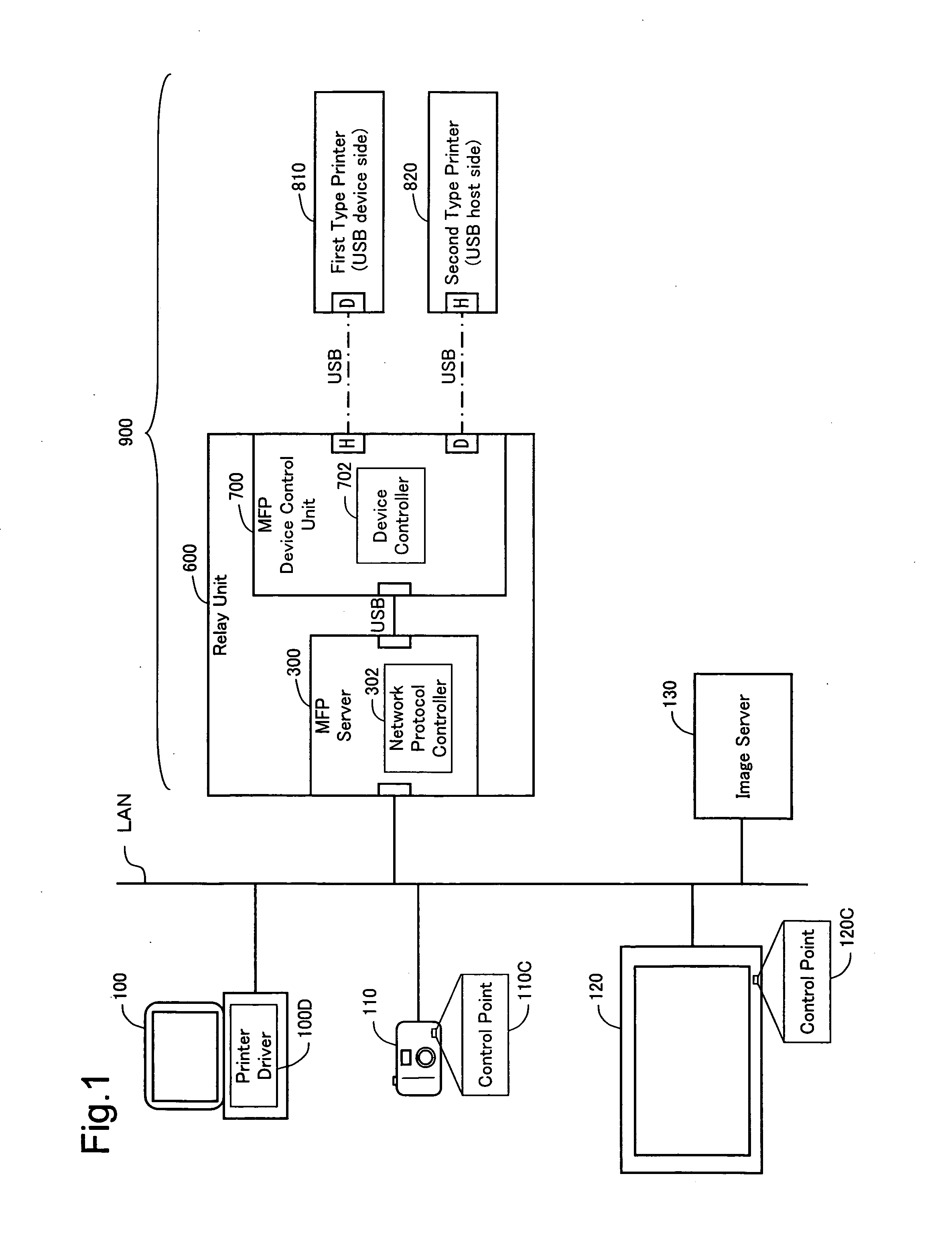
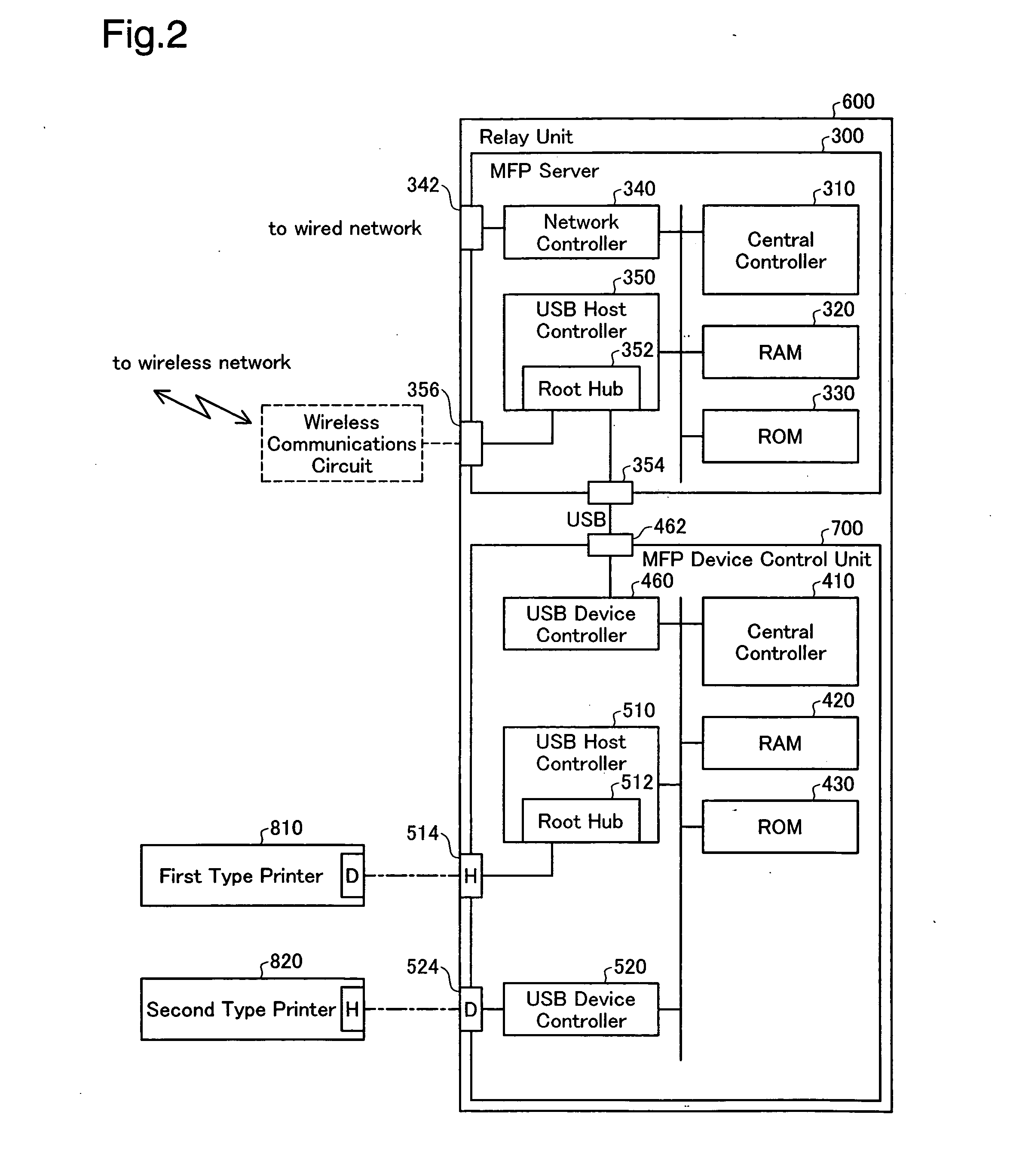
[0010] With this relay device, a print request message is converted to printer data according to a universal standard acceptable by the device unit that is actually connected to the relay device, and the converted data is supplied to the device unit, whereby it is possible for the print request message to be relayed appropriately to the device unit. Since the printer data is in accordance with a universal standard, there is no need for the relay device to be configured to create data in a format unique to individual printers, thus facilitating implementation of the relay device.

Problems solved by technology

However, to date, there has not been sufficient research as to how such a relay device would be achieved.
In particular, while it is possible for device units having a wide range of functions to be connected to a relay device, there has yet to be devised a satisfactory design for how to operate a device unit when a print request message is received from a client.

Method used


Image

  • Network plug-and-play compliant network relay device
  • Network plug-and-play compliant network relay device
  • Network plug-and-play compliant network relay device

Examples


modified example 1

D1. Modified Example 1

[0065] It is possible to use a device unit containing several devices as the device unit connected to the relay unit 600. It is also possible to use a device unit that includes only one non-printer device (e.g. mass storage). For example, where a device unit having only a mass storage device has been connected to the relay unit 600, the print request message may be converted to printer data according to a pre-selected universal standard (e.g. JPEG data), and sent from the relay unit 600 to the mass storage device for storage. As will be apparent from this description, in preferred practice there may be employed an arrangement whereby when the relay unit 600 receives from a client a print request message describing in markup language an image for printing, printer data according to universal standard acceptable by the actually connected device unit will be created and supplied to the device unit. Herein, “universal standard” refers not to the proprietary standar...

modified example 2

D2. Modified Example 2

[0066] In the preceding embodiment, it is possible to selectively connect one of the two types of device units 810, 820 to the relay unit 600, but the relay unit 600 may be configured so that it is possible to connect only one type of device unit (e.g. the first type printer 810). In this case as well, as long as printer data acceptable to the actually connected device unit can be created within the relay unit 600, it will be possible to achieve the advantage of not having to modify implementation of the MFP device control unit 700 depending on the type of device unit connected.

modified example 3

D3. Modified Example 3

[0067] In the preceding embodiment, some of the arrangements realized through hardware in the preceding embodiments may instead be replaced by software; conversely, some of the arrangements realized through software may be replaced by hardware.


PUM


Abstract

A network relay device, which is compliant with network plug-and-play, is used for relaying between a network and a device unit having one or more service devices that provide a service in response to a request from a client on the network. The network relay device includes a data conversion module that, upon receiving from a client a print request message describing in markup language an image for printing, converts the print request message to data for use by the device unit and supplies the converted data to the device unit. The data conversion module creates, as the data for use by the device unit, printer data according to a universal standard acceptable by the device unit.

Description

CROSS-REFERENCE TO RELATED APPLICATIONS [0001] The present application claims the priority based on Japanese Patent Application No. 2005-5229 filed on Jan. 12, 2005, the disclosure of which is hereby incorporated by reference in its entirety. BACKGROUND OF THE INVENTION [0002] 1. Field of the Invention [0003] The present invention relates to control technology for a network plug-and-play compliant network relay device. [0004] 2. Description of the Related Art [0005] Plug-and-play is a well-known technology that enables peripheral devices to be connected to a computer or disconnected from a computer at arbitrary timing after startup of the computer. In recent years, extension of plug-and-play technology to networks has led the development of Universal Plug and Play (hereinafter UPnP; UPnP is a trademark of UPnP Implementers Corporation). The use of UPnP enables network devices to be connected to a network or disconnected from the network at arbitrary timing. Herein, the architecture ...

Claims


Application Information

Patent Timeline
IPC IPC(8): G06F3/12
CPCG06F3/1204G06F3/1206G06F3/1246H04N2201/001H04N1/00222H04N1/00233G06F3/1288
Inventor OSHIMA, YASUHIROTAKADA, YOJI
Owner SEIKO EPSON CORP
Learn More