Supercharge Your Innovation With Domain-Expert AI Agents!

Process controls methods and apparatuses for improved image consistency

a technology of image consistency and control method, applied in the field of printing system, can solve the problems of difficulty in adjusting the intensity of the image, so as to improve the consistency of image consistency and improve the consistency of multiple engines

Inactive Publication Date: 2007-11-15
XEROX CORP
View PDF74 Cites 7 Cited by
  • Summary
  • Abstract
  • Description
  • Claims
  • Application Information

AI Technical Summary

Benefits of technology

[0033] In accordance with one aspect, a method is disclosed. Density or reflectance targets for respective first and second marking engines of a document processing system are determined. A series of control patches is printed with the respective first and second marking engines. Relative reflectance values of the control patches printed with the first and second engines are measured with first and second engine sensors. A first marking engine relative reflectance error value for each control patch is determined based at least on corresponding first engine relative reflectance value and first engine target relative reflectance value. A second marking engine relative reflectance error value for each control patch is determined based at least on corresponding second engine relative reflectance value and second engine target relative reflectance value. Based at least on one of the first and second engine relative reflectance error value, at least one of the first and second engine relative reflectance target is adjusted. Based at least on the adjusted target, an image quality control of the document processing system is improved.
[0034] In accordance with another aspect, a document processing system is disclosed. Each marking engines prints a series of control patches of various area coverage, each marking engine having at least one actuator. First and second patch sensors each measures black tone area coverage voltage value from each control patch printed with a respective first and second marking engine. A relative reflectance determining device determines relative reflectance values of each respective control patch printed with the first and second marking engine. An engine error determining algorithm determines a first marking engine relative reflectance error value for each control patch, based at least on corresponding first engine relative reflectance value and first engine target relative reflectance value, and a second marking engine relative reflectance error value for each control patch, based at least on corresponding second engine relative reflectance value and second engine target relative reflectance value. An adjusting algorithm adjusts at least the relative reflectance target of at least one of the first and second marking engine based at least on the respective relative reflectance error value to improve image quality control in the document processing system.
[0035] In accordance with another aspect, a document processing system is disclosed. Each marking engines prints a series of control patches of each preselected area coverage. First and second patch sensors, each measures black tone area coverage voltage values from each control patch printed with at least first and second marking engines. A computer is programmed to perform steps of: determining a relative reflectance value of each control patch printed with the first engine; determining a relative reflectance value of each control patch printed with the second engine; determining a first marking engine relative reflectance error value for each control patch based at least on corresponding first engine relative reflectance value and first engine target relative reflectance value; determining a second marking engine relative reflectance error value for each control patch based at least on corresponding second engine relative reflectance value and second engine target relative reflectance value; based at least on one of the first and second engine relative reflectance error value, adjusting at least one of the first engine and second engine relative reflectance target; and based at least on the adjusted target, improving an image quality control of the document processing system.

Problems solved by technology

However, many factors, such as temperature, humidity, ink or toner age, and / or component wear, tend to move the output of a printing system away from the ideal or target output.
While a user might not ever notice the subtle variations when reviewing the output of either engine alone, when the combined output is compiled and displayed adjacently, the variation in intensity from one print engine to another may become noticeable and be perceived as an issue of quality by a user.
However, this approach requires a user intervention and the scanner to scan the test patches.
However, such approach is complex as it involves substantial software development as well as elaborate scheduling of test patches to not interfere with the print job.
However, the aforementioned patents are not concerned with methods for improving or achieving image consistency between or among a plurality of marking engines.

Method used


Image

  • Process controls methods and apparatuses for improved image consistency
  • Process controls methods and apparatuses for improved image consistency
  • Process controls methods and apparatuses for improved image consistency

Examples


Embodiment Construction

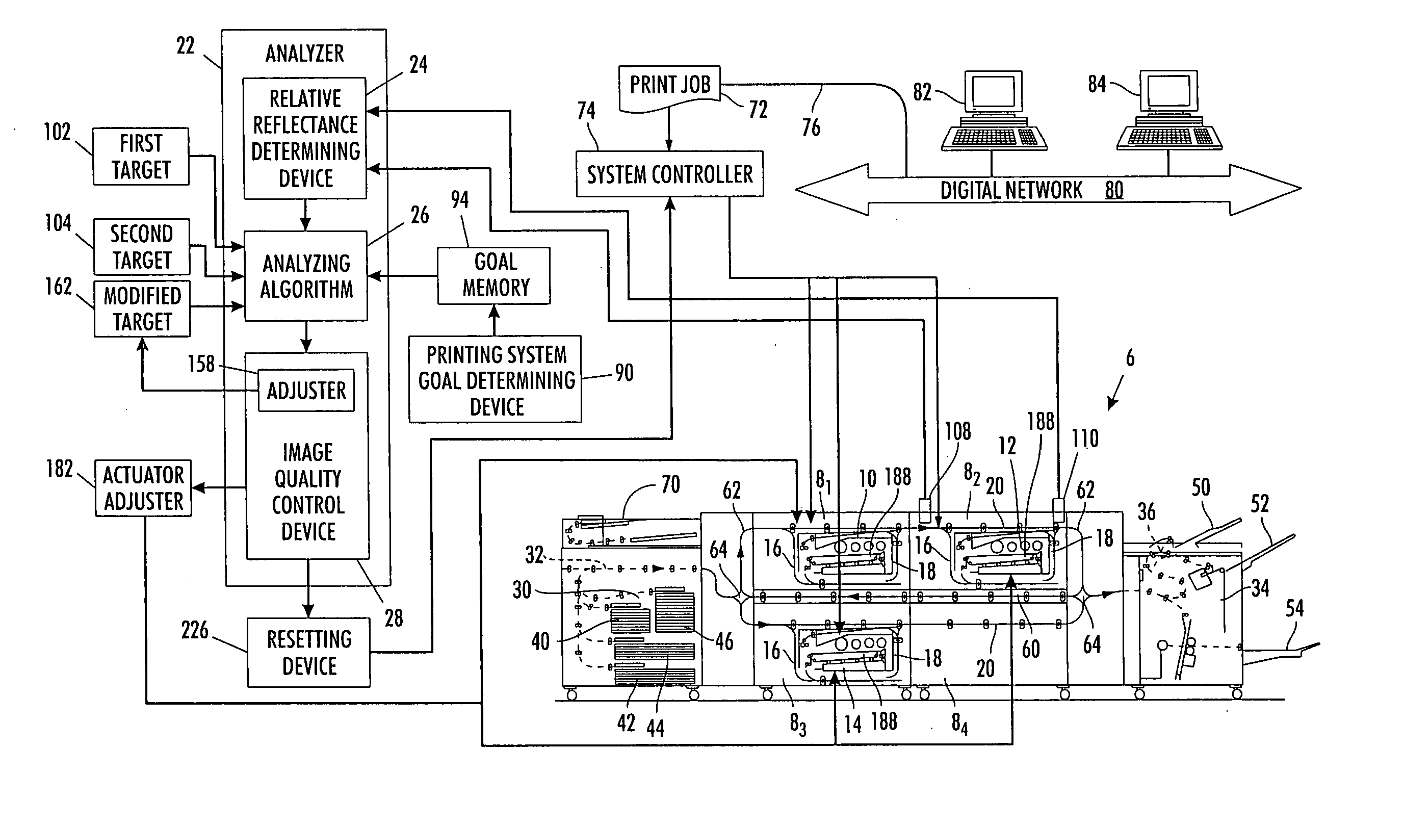
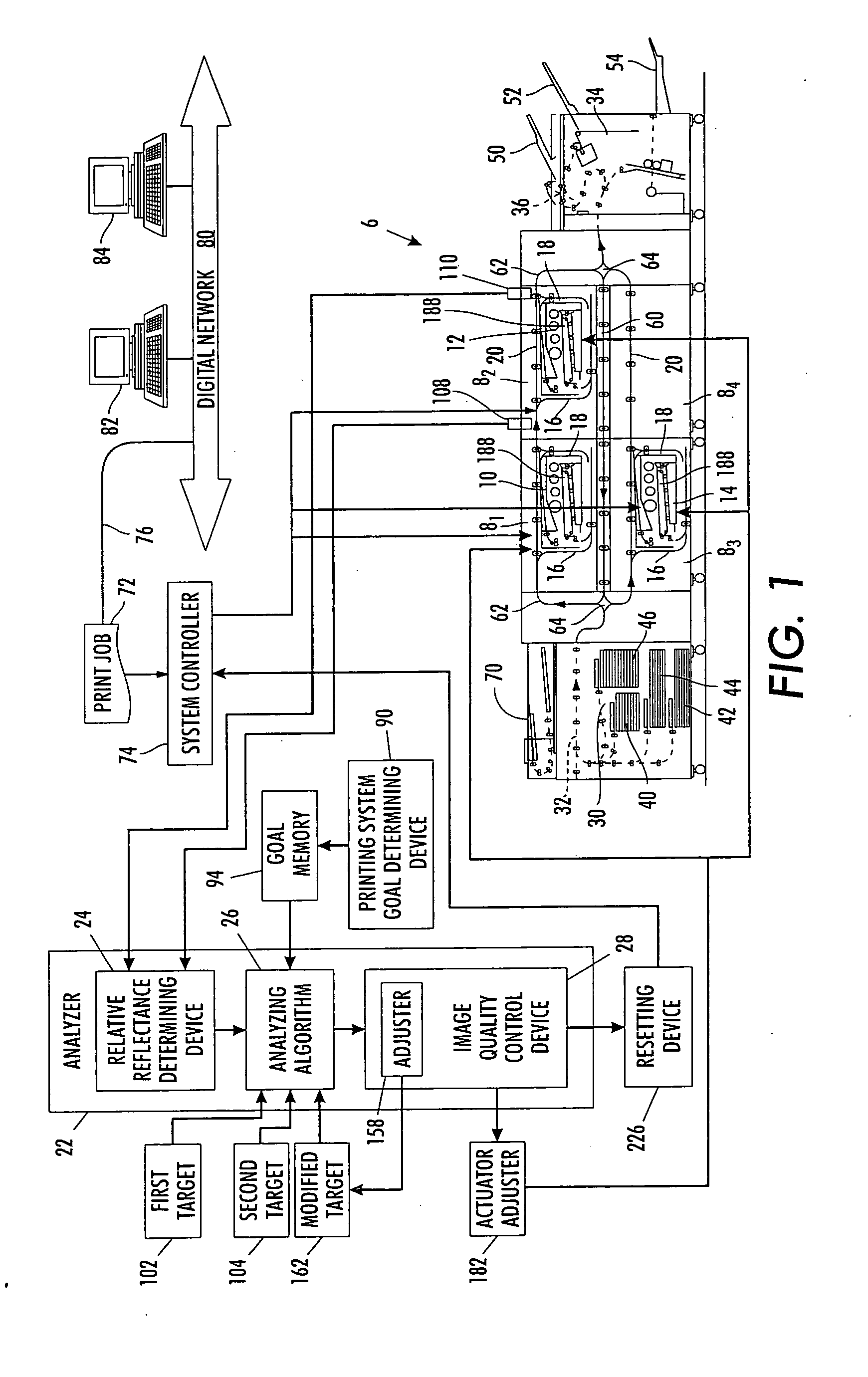
[0044] With reference to FIG. 1, an example printing or document processing system 6 includes first, second, . . . , nth marking engine processing units 81, 82, 83, . . . , 8n each including an associated first, second, . . . , nth marking or print engines or devices 10, 12, 14 and associated entry and exit inverter / bypasses 16, 18. In some embodiments, marking engines are removable. For example, in FIG. 1, an integrated marking engine and entry and exit inverter / bypasses of the processing unit 84 are shown as removed, leaving only a forward or upper paper path 20. In this manner, for example, the functional marking engine portion can be removed for repair, or can be replaced to effectuate an upgrade or modification of the printing system 6. While three marking engines 10, 12, 14 are illustrated (with the fourth marking engine being removed), the number of marking engines can be one, two, three, four, five, or more. Providing at least two marking engines typically provides enhanced ...


PUM


Abstract

Density or reflectance targets for respective first and second marking engines of a document processing system are determined. A series of control patches is printed with the respective first and second marking engines. Relative reflectance values of each control patch printed with the first and second engines are determined. First marking engine relative reflectance error values of each control patch and second marking engine relative reflectance error values of each control patch are determined correspondingly based at least on (a) corresponding first engine relative reflectance value and target relative reflectance value and (b) corresponding second engine relative reflectance value and target relative reflectance value. Based at least on one of the first and second marking engine relative reflectance error values, at least one of the first and second engine relative reflectance targets is adjusted. Based at least on the adjusted target, an image quality control of the document processing system is improved.

Description

CROSS REFERENCE TO RELATED PATENTS AND APPLICATIONS [0001] The following patent and applications, the disclosures of each being totally incorporated herein by reference are mentioned: [0002] U.S. application Ser. No. 10 / 917,676 (Attorney Docket A3404-US-NP), filed Aug. 13, 2004, entitled “MULTIPLE OBJECT SOURCES CONTROLLED AND / OR SELECTED BASED ON A COMMON SENSOR,” by Robert M. Lofthus, et al.; [0003] U.S. application Ser. No. 10 / 999,326 (Attorney Docket 20040314-US-NP), filed Nov. 30, 2004, entitled “SEMI-AUTOMATIC IMAGE QUALITY ADJUSTMENT FOR MULTIPLE MARKING ENGINE SYSTEMS,” by Robert E. Grace, et al.; [0004] U.S. application Ser. No. 11 / 070,681 (Attorney Docket 20031659-US-NP), filed Mar. 2, 2005, entitled “GRAY BALANCE FOR A PRINTING SYSTEM OF MULTIPLE MARKING ENGINES,” by R. Enrique Viturro, et al.; [0005] U.S. application Ser. No. 11 / 081,473 (Attorney Docket 20040448-US-NP), filed Mar. 16, 2005, entitled “PRINTING SYSTEM,” by Steven R. Moore; [0006] U.S. application Ser. No. ...

Claims


Application Information

Patent Timeline
IPC IPC(8): G03G15/00
CPCG03G2215/00021G03G15/5062
Inventor MONGEON, MICHAEL C.MO, SONG-FENGCOSTANZA, DANIEL W.
Owner XEROX CORP
Features
  • R&D
  • Intellectual Property
  • Life Sciences
  • Materials
  • Tech Scout
  • Unparalleled Data Quality
  • Higher Quality Content
  • 60% Fewer Hallucinations
Learn More