Device and method for the transferring of grain from a grain bin

a technology for grain bins and devices, applied in agriculture tools and machines, building types, construction, etc., can solve the problems of more difficult, necessary to minimize and achieve the effect of reducing the risk of deformation of the bin wall and minimizing the loading on the bin wall

Inactive Publication Date: 2007-11-15
REM ENTERPRISES INC
View PDF27 Cites 16 Cited by
  • Summary
  • Abstract
  • Description
  • Claims
  • Application Information

AI Technical Summary

Benefits of technology

[0012] The advantage of the present invention is that it provides an improved device and method for transferring grain or other particulates from a grain bin.
[0013] A still further advantage of the present invention is that it provides an improved device and method for effectively providing for the transfer of grain or other particulates from a grain bin, while minimizing the loading on the bin walls, and thus reducing the risk of deformation of the bin wall during the loading and unloading processes.

Problems solved by technology

During the removal of grain from the bin, continuously unloading the bin from the center of the grain pile, while necessary to minimize the risk of deformation of the bin wall, is more difficult.

Method used


Image

  • Device and method for the transferring of grain from a grain bin
  • Device and method for the transferring of grain from a grain bin
  • Device and method for the transferring of grain from a grain bin

Examples


Embodiment Construction

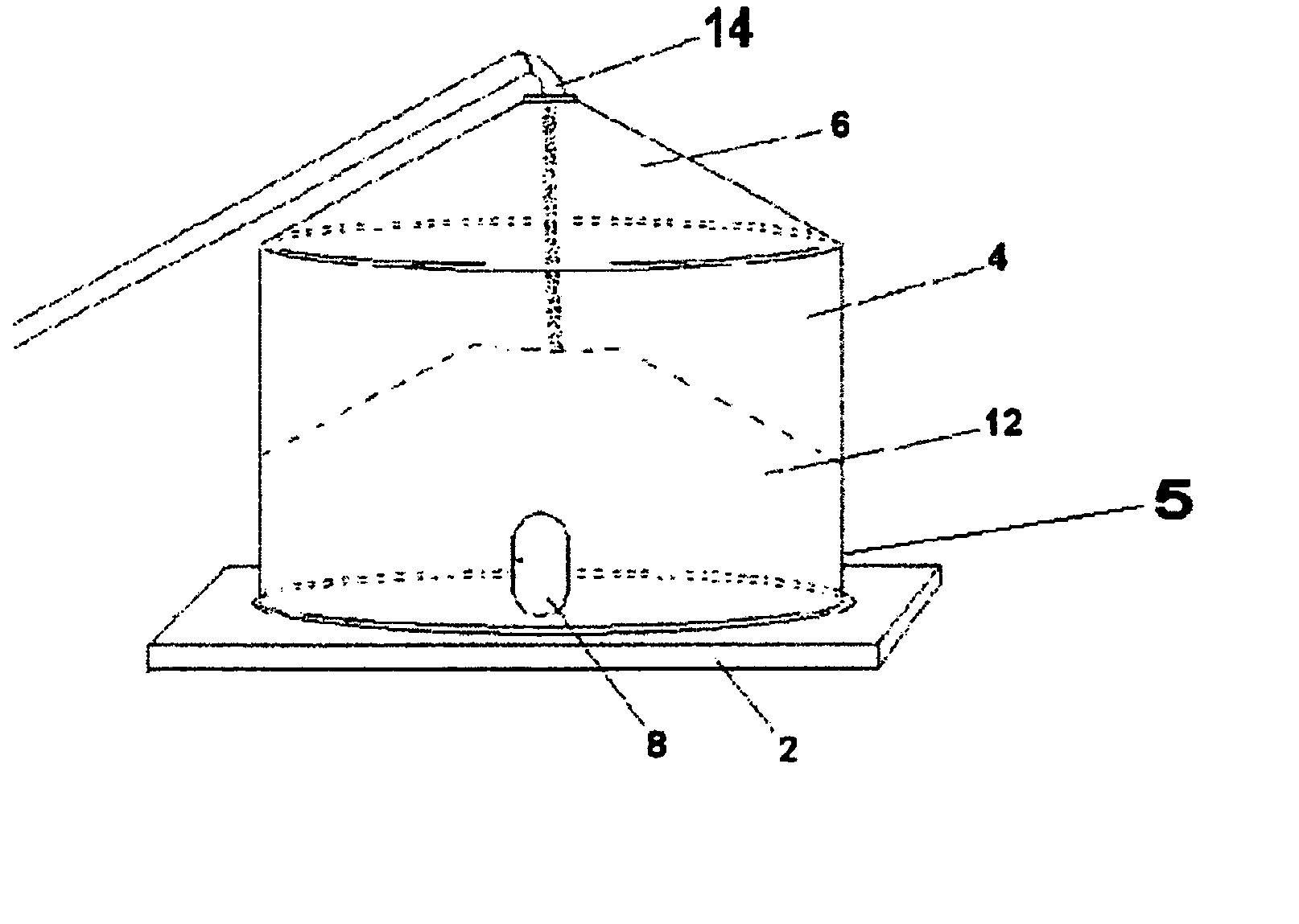
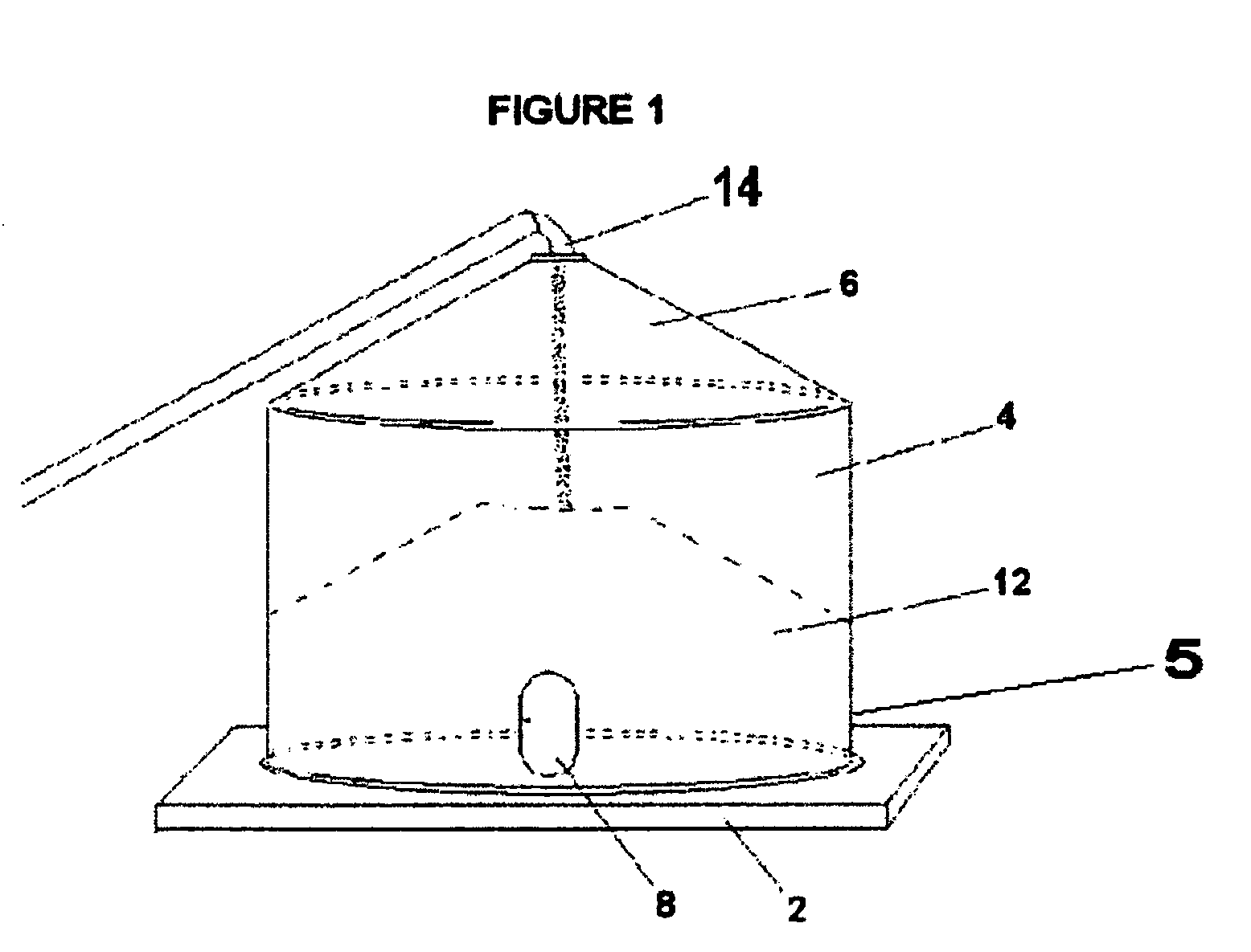
[0028] Referring to FIG. 1, positioned upon a concrete pad 2, is a typical grain bin 4, it being understood that grain bins may be positioned upon other suitable pads or materials known to a person skilled in the art. The vertical walls 5 and conical roof 6 of the typical grain bin 4 are generally made of corrugated stainless steel or other suitable material, known to a person skilled in the alt. An access door 8 provides access for personnel and equipment into the interior of the grain bin 4 and an access port 10 at the top of the grain bin 4 permits grain to be transferred from a conveyor system 14 into the interior of the grain bin 4 for storage, which typically forms a pile 12 generally centered within the grain bin 4.

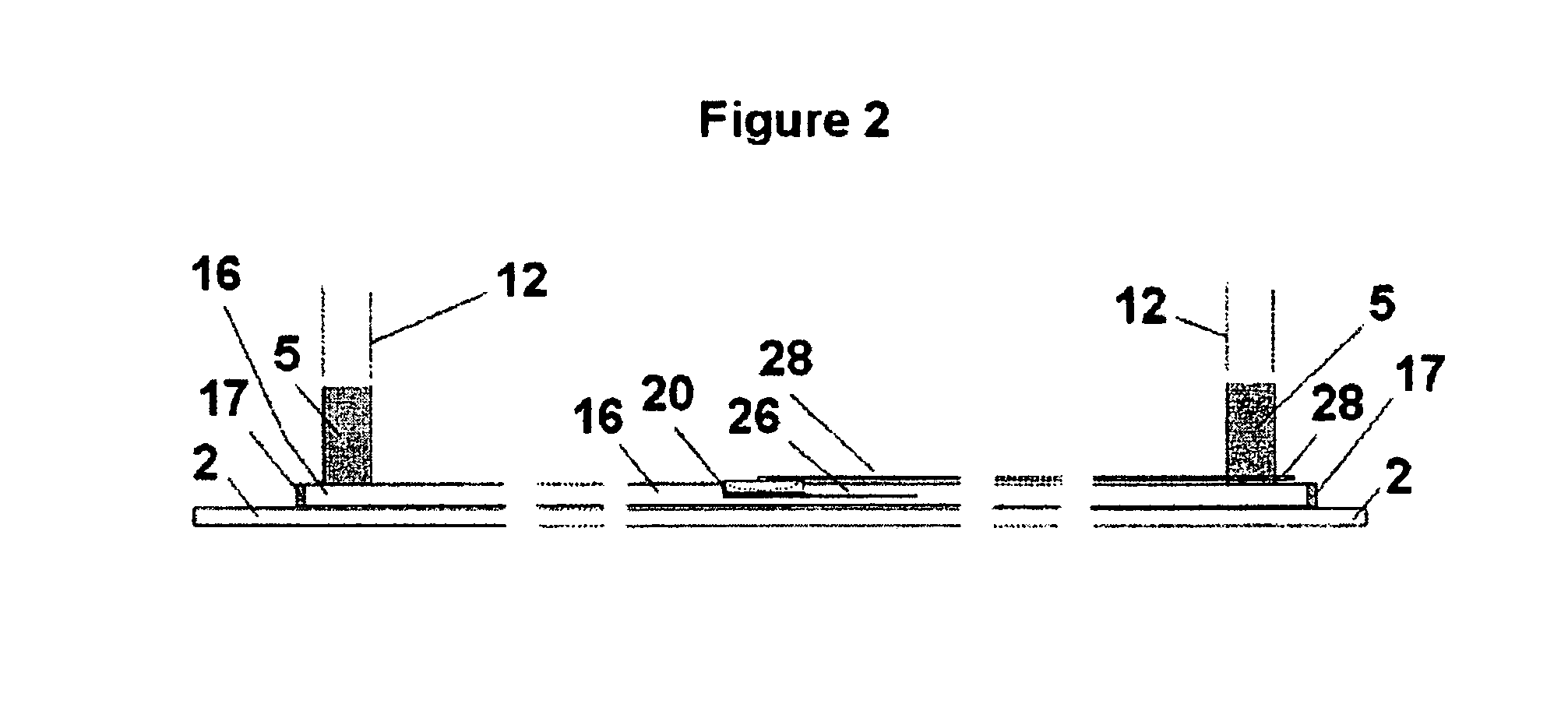
[0029] Referring to FIG. 2, a metal tube 16 extends across the concrete pad 2 (or other floor material for the bin, hereinafter referred to as the “concrete pad”), and is securely anchored thereto by means of anchors, straps, bolts or other devices known to a pers...


PUM


Abstract

An improved device and method for transferring grain or other particulates from a grain bin. The invention comprises an inlet positioned in a sidewall of the grain bin, and an outlet in another sidewall of the grain bin opposite the inlet. A grain transfer tube is inserted through each of the inlet and the outlet, the tube having at least one opening therein for permitting grain in the grain bin to enter into the interior of the tube. A blower for communicating with the grain transfer tube is positioned at an end of the grain transfer tube positioned at the inlet, and provides an air stream the tube. A suction hose is coupled with the outlet, to create, in combination with the blower, a vacuum force for drawing the grain in the grain bin to enter into the interior of the tube, and then propelling the drawn grain along the tube through the outlet to a remote location.

Description

FIELD OF THE INVENTION [0001] The present invention relates to the transferring of grain or other particulates, and particularly to the transferring of grain or other particulates from a grain bin or other storage location. BACKGROUND OF THE INVENTION [0002] Grain bins, which generally are in a cylindrical configuration and having a conically shaped roof can be in excess of 40 feet in diameter and in excess of 40 feet in height, storing for example, in excess of 30,000 bushels of grain or other particulate material. The bin floor, for example, may be formed by a poured concrete slab. The bin walls which are securely anchored to the bin floor are generally made of curved, corrugated stainless steel panels which are bolted or joined together to form a continuous curved wall for the bin. An access door at the bottom of the bin is generally provided to allow access for workers and equipment onto the bin floor, for example, when the bin is substantially empty. The roof of the bin will ge...

Claims


Application Information

Patent Timeline
Patent Type & Authority Applications(United States)
IPC IPC(8): E04H7/22
CPCA01F25/2018B65G65/40B65G53/28
Inventor SONNTAG, BOB
Owner REM ENTERPRISES INC
Why Eureka
Try Eureka