
Apparatus for correcting presbyopia

a presbyopia and apparatus technology, applied in the field of apparatus for correcting presbyopia, can solve the problems of distorted vision, inability to achieve good visual acuity, and inability to correct presbyopia with photorefractive surgery equipment, and achieve the effect of effective and accurate correction

Inactive Publication Date: 2007-11-15
PINELLI ROBERTO
View PDF4 Cites 47 Cited by
  • Summary
  • Abstract
  • Description
  • Claims
  • Application Information

AI Technical Summary

Benefits of technology

[0012] Another purpose of the invention is to produce an apparatus for correcting presbyopia which offers extremely effective and accurate correction.

Problems solved by technology

The various vision defects (myopia, hypermetropia and astigmatism) have their origin in conditions of the cornea which prevent images from being focused on the retina and for this reason do not permit good visual acuity such as is present in emmetropic individuals (who have no vision defects).
Each of these conditions prevents images from being brought into focus on the retina and consequently produces distorted vision.
At present, on the other hand, no photorefractive surgery equipment is capable of correcting presbyopia, a defect which affects almost all of the population and unlike the common refraction defects is a malfunction of the crystalline lens and of the accommodation muscles, resulting from the normal ageing process.
Consequently, presbyopia is generally corrected only by means of contact lenses or lenses fitted to spectacles, but this does of course tie the user to daily use of a particular artificial corrective device, which is sometimes inconvenient and approximate in correction.

Method used


Image

  • Apparatus for correcting presbyopia
  • Apparatus for correcting presbyopia
  • Apparatus for correcting presbyopia

Examples


example 1

[0034] Emmetropic patient (with good normal distant vision) suffering from presbyopia (+2; age between 50 and 60 years).

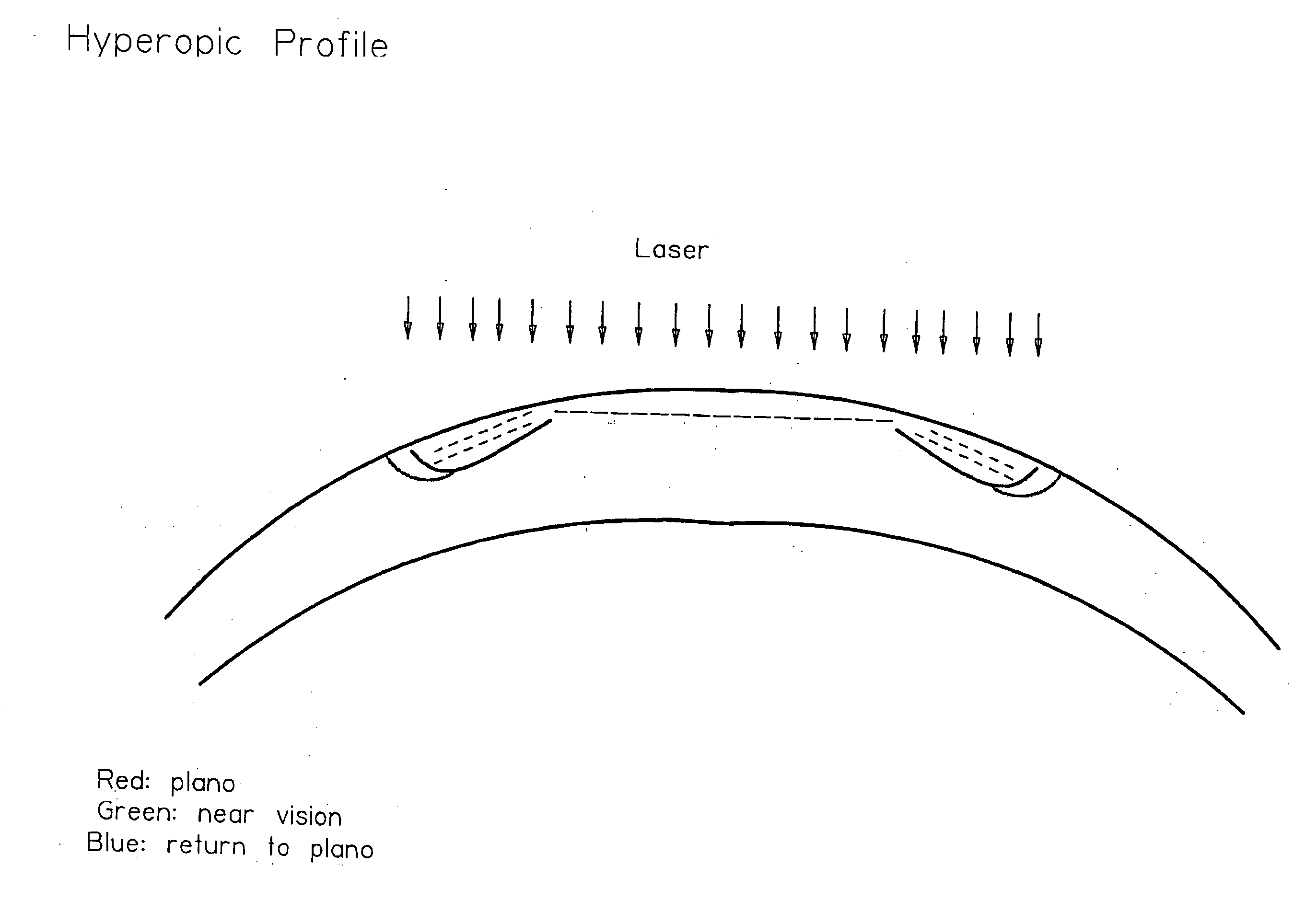
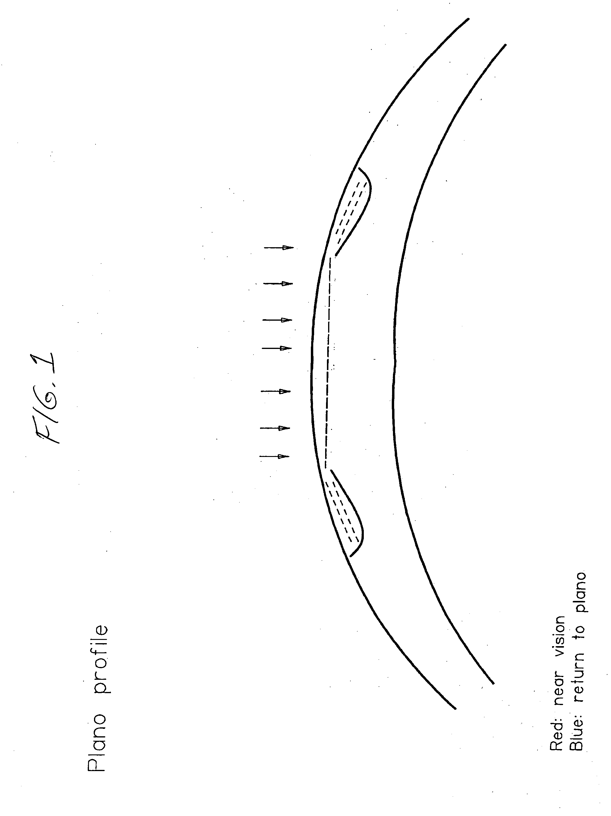
[0035] Sequence of machine instructions: [0036] key in data relating to the extent of the area of intervention: 6 mm; [0037] key in data relating to the first depth of intervention: such as to reduce the presbyopic defect by +1; [0038] first activation of the laser beam (corresponding to the execution of a first ablation over the whole optical area considered); [0039] key in data relating to the extent of the second area of intervention: 6.5 mm; [0040] key in data relating to the second depth of intervention: such as to reduce the presbyopic defect by another +1; [0041] second activation of the laser beam (corresponding to the execution of a second ablation over the whole 6.5 mm optical area);

[0042] Correction of the induced myopia defect of 2 dioptres: [0043] key in data relating to the extent of the third area of intervention: 5.2 mm; [0044] key in data relatin...

example 2

[0049] Myopic patient (−2 dioptres) also suffering from presbyopia (+2.5; age between 60 and 70 years)

[0050] Sequence of machine instructions: [0051] key in data relating to the extent of the first area of intervention: 5.6 mm; [0052] key in data relating to the first depth of intervention: such as to reduce the myopic defect by −1; [0053] first activation of the laser beam (corresponding to the execution of a first ablation over the whole optical area considered); [0054] key in data relating to the extent of the second area of intervention: 5.8 mm; [0055] key in data relating to the second depth of intervention: such as to reduce the myopic effect by another −1; [0056] second activation of the laser beam (corresponding to the execution of a second ablation over the whole 5.8 mm optical area);

[0057] Correction of the presbyopic defect: [0058] key in data relating to the extent of the third optical intervention area: 6 mm; [0059] key in data relating to the third depth of intervent...

example 3

[0071] Patient with hypermetropia of +1 and suffering from presbyopia (+1; age between 40 and 45 years)

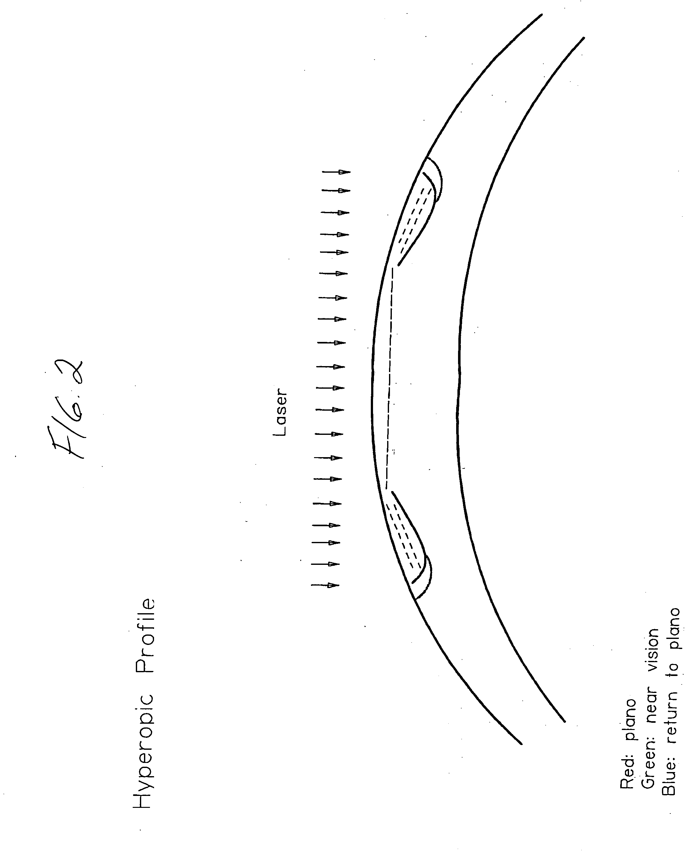
[0072] Sequence of machine instructions: [0073] key in data relating to the extent of the first optical intervention area: 6 mm; [0074] key in data relating to the first depth of intervention: such as to reduce the hypermetropic defect by +1; [0075] first activation of the laser beam (corresponding to the execution of a first ablation over the whole 6 mm optical area); [0076] key in data relating to the extent of the second area of intervention: 6.5 mm; [0077] key in data relating to the second depth of intervention: such as to reduce the presbyopic defect (+1); [0078] second activation of the laser beam (corresponding to the execution of a second ablation over the whole 6.5 mm optical area);

[0079] Correction of the induced hypermetropia defect: [0080] key in data relating to the extent of the third area of intervention: 5.2 mm; [0081] key in data relating to the third depth of i...


PUM


Abstract

The apparatus for correction presbyopia comprises a photorefractive surgery laser beam device operating by means of a control program capable of managing the following instructions: extent of at least a first circular area of intervention, which determines at least first laser beam aiming parameters; at least a first depth of intervention in the first area of intervention, which determines at least first intensity and / or duration parameters for the laser beam; at least a first activation of the laser beam with the first aiming parameters an the first intensity and / or duration parameters; extent of at least a second circular area of intervention, concentric, superimposed and with a diameter different from the first area of intervention, which determines at least second laser beam aiming parameters; at least a second depth of intervention in the second area of intervention, which determines at least second intensity and / or duration parameters for the laser beam; and at least a second activation of the laser beam, following on from the first activation, with the second aiming parameters and the second intensity and / or duration parameters.

Description

CROSS REFERENCE TO THE RELATED APPLICATIONS [0001] This application is a continuation-in-part of International Application No. PCT / EP2005 / 006736, designating the United States.TECHNICAL FIELD OF THE INVENTION [0002] The present invention relates to an apparatus for correcting presbyopia. BACKGROUND ART [0003] Vision defects (refraction defects) such as myopia, hypermetropia, astigmatism and presbyopia are traditionally corrected by means of lenses fitted to spectacles or by means of contact lenses. [0004] With the development of knowledge in the field of eye surgery and with the introduction of diagnostic and surgical instruments of various types, among which the excimer laser and the microkeratome have played a leading role, refractory surgery has truly become a branch of ophthalmology and a specialism which now makes it possible to reduce considerably, and in most cases eliminate, the use of artificial optical devices (spectacles and contact lenses) to correct myopia, hypermetropi...

Claims


Application Information

Patent Timeline
IPC IPC(8): A61B18/20
CPCA61F9/008A61F2009/00895A61F2009/00872A61F9/00808
Inventor PINELLI, ROBERTO
Owner PINELLI ROBERTO
Learn More