Motor vehicle steering system

Inactive Publication Date: 2007-11-15
JTEKT CORP
View PDF24 Cites 15 Cited by
  • Summary
  • Abstract
  • Description
  • Claims
  • Application Information

AI Technical Summary

Benefits of technology

[0011] A purpose of the present invention is to provide a motor vehicle steering syst

Problems solved by technology

In a condition where a vehicle travels straight on a rutted road which is uneven surface road where wheel ruts or wheel track furrows (depressions left after wheels of a vehicle passed) are formed, the conventional stabilization control of a vehicle behavior cannot sufficiently work.
That is, on a rutted road, a motor vehicle is prone to wobble and

Method used


Image

  • Motor vehicle steering system
  • Motor vehicle steering system
  • Motor vehicle steering system

Examples


first embodiment

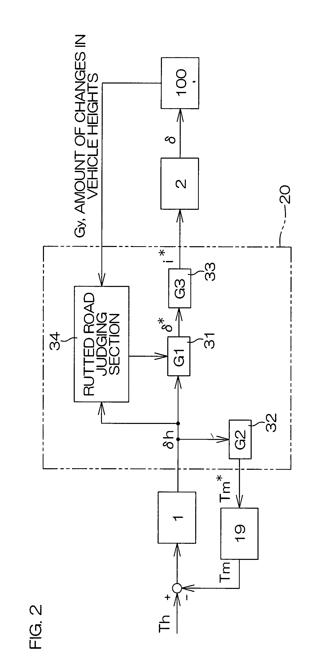
[0059]FIG. 5 is a control block diagram for explaining a second embodiment of this invention. In the explanation of this embodiment, while referring to FIG. 1 used for explanation of the afore-mentioned first embodiment, in FIG. 5, the same reference numerals as those of FIG. 2 are used for the parts corresponding to the ones in the afore-mentioned FIG. 2.

[0060] In this embodiment, a reaction force actuator 19 is controlled so as to make operation reaction force given to a steering wheel 1 when traveling on a rutted road become smaller than when traveling on an ordinary road. By this, steering enhancement control or steering support control to reduce burden of a driver while traveling on a rutted road is performed.

[0061] More specifically, while a target steering angle computing section 31 computes a target steering angle δ* using the afore-mentioned formula (1) regardless of whether traveling on a rutted road or not, a target reaction force torque computing section 32 sets a small...

third embodiment

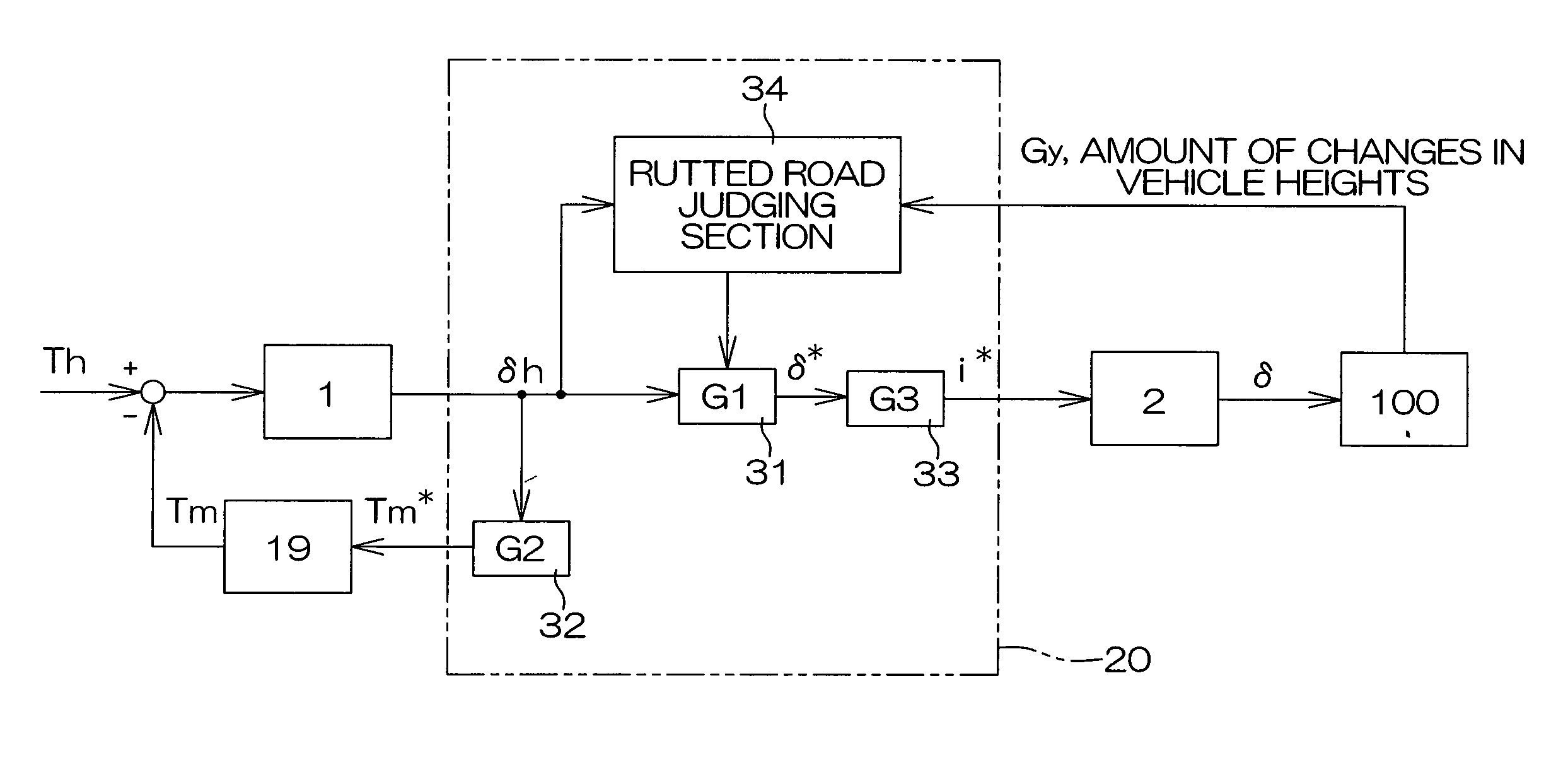
[0064]FIG. 7 is a control block diagram for explaining the present invention. In this explanation of the embodiment, while referring to FIG. 1 used for explanation of the afore-mentioned first embodiment, in FIG. 7, the same reference numerals as those of FIG. 2 are used for the parts corresponding to the ones in the afore-mentioned FIG. 2.

[0065] In this embodiment, while vehicle behavior stabilization control is performed by control of a steering angle δ, a reaction force actuator 19 is controlled so as to make operation reaction force given to a steering wheel 1 when traveling on a rutted road become smaller than when traveling on an ordinary road. By this, steering enhancement control or steering support control to reduce burden of a driver while traveling on a rutted road is performed.

[0066] In this embodiment, using behavior index value D=K1·Gy+K2γ·V (first-order linear coupling of lateral acceleration and yaw rate) as an index expressing vehicle behavior, vehicle behavior sta...

fourth embodiment

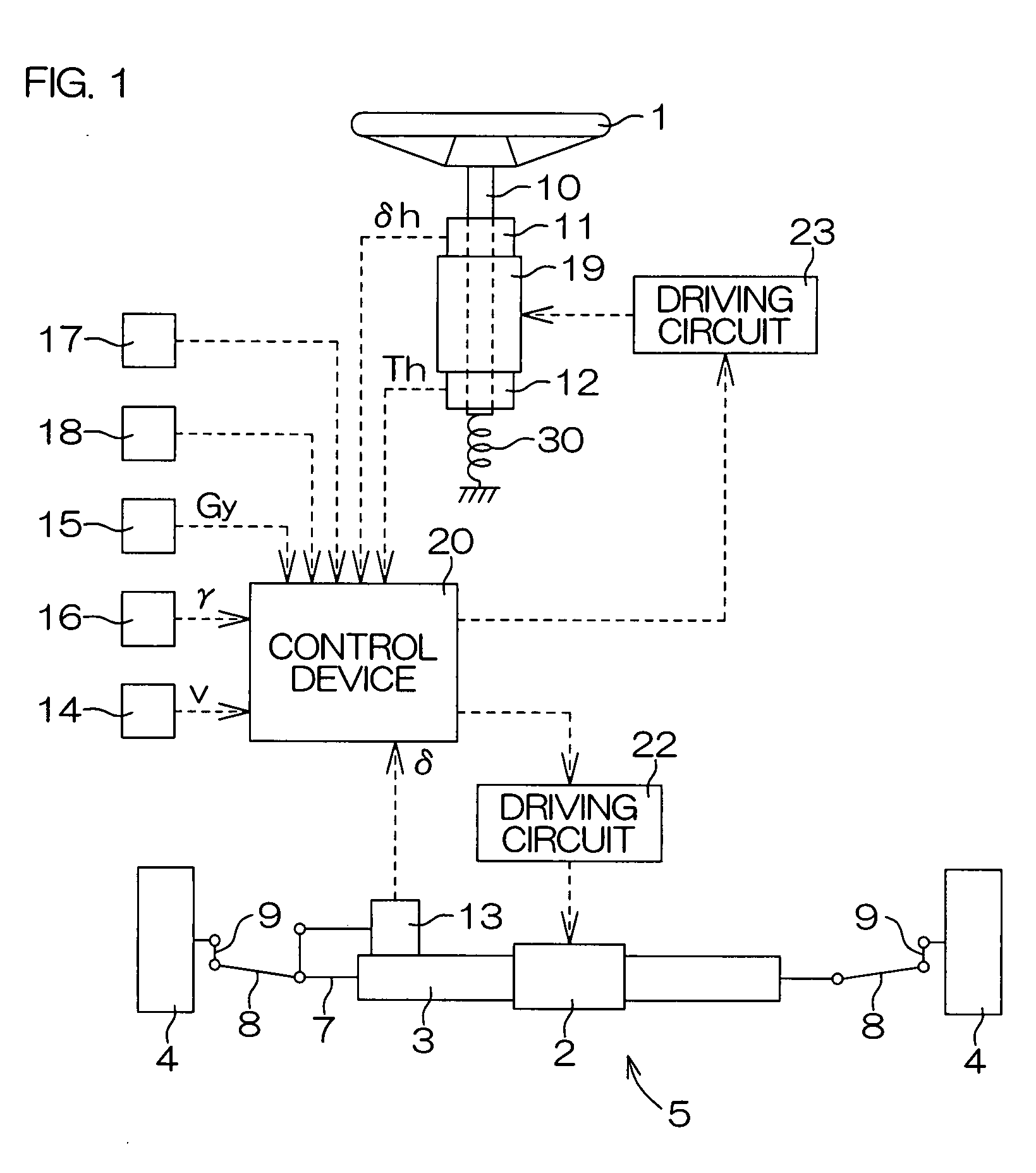
[0086]FIG. 8 is an explanatory diagram for explaining configuration of an electric power steering apparatus as a motor vehicle steering system according to the present invention. Operation torque added to a steering wheel 61, which serves as a steering member, is mechanically transmitted to a steering mechanism 63 via a steering shaft 62. To a steering mechanism 3, steering assist force is transmitted from an electric motor M (steering assist force generation unit, operation reaction force adjusting unit) as a steering assist actuator via a reduction mechanism (not shown) or by a direct drive system.

[0087] The steering shaft 62 is divided into an input shaft 62A connected to the steering wheel 61 side and an output shaft 62B connected to the steering mechanism 63 side, and the input shaft 62A and the output shaft 62B are connected with each other by a torsion bar 64. The torsion bar 64 generates distortion in accordance with operation torque Th, and direction and amount of the torsi...


PUM


Abstract

A motor vehicle steering system steers vehicle wheels in response to the operation of an operation member for steering a vehicle. The system includes a rutted road judging unit which judges whether the vehicle is driving on a rutted road or not, and a steering enhancement control unit which enhances steering of vehicle wheels in response to operation of the operation member when the rutted road judging unit judges that the vehicle is driving on a rutted road than when the rutted road judging unit judges that the vehicle is not driving on a rutted road.

Description

BACKGROUND OF THE INVENTION [0001] 1. Field of the Invention [0002] The present invention relates to a motor vehicle steering system by which a steerable vehicle wheel is steered according to operation of an operation member. [0003] 2. Description of Related Art [0004] An example of a motor vehicle steering system is an electric power steering apparatus in which steering assist force generated by an electric motor is transmitted to a steering mechanism. An electric power steering apparatus is equipped with a control device which drives an electric motor according to operation torque which is applied to a steering wheel by a driver. Due to this structure, appropriate steering assist force according to the operation torque can be generated. [0005] Another example of a motor vehicle steering system is a steer-by-wire system (refer to EP1097855 A2). In a steer-by-wire system, there is no mechanical connection between a steering wheel and a steering mechanism. In this system, while opera...

Claims


Application Information

Patent Timeline
IPC IPC(8): B62D6/00
CPCB62D6/003B62D6/008B62D6/007
Inventor HAYAMA, RYOUHEINAKANO, SHIROKADA, TOMOYASU
Owner JTEKT CORP
Why Eureka
Try Eureka