
Multiple-use goniometer

a goniometer and multiple use technology, applied in the field of multiple use goniometers, can solve the problems of indicating that arm measurements are not feasible, devices tend to lose liquid, and the number of significant problems remains

Inactive Publication Date: 2007-11-22
QUANTUM TMT
View PDF10 Cites 23 Cited by
  • Summary
  • Abstract
  • Description
  • Claims
  • Application Information

AI Technical Summary

Problems solved by technology

Gravity-operated liquid bubble devices have also been used to measure range of motion of wrist rotation and the like, where indicating arm measurements are not feasible.
However, over time these devices tend to lose their liquid owing to leakage, and become inoperative.
Despite the plethora of prior goniometers, a number of significant problems remain.
One such difficulty is that a therapist must have and maintain a variety of different goniometers useful for range of motion measurements of various different body parts.
This creates storage and handling problems, particularly if the therapist travels to the homes of patients.
This means that the therapist does not have a free hand to assist the patient, which is sometimes necessary with elderly or burn patients.
Moreover, such two-handed operation means that the therapist does not have a free hand to record range of motion results.
Again, this materially increases the complexity and cost associated with range of motion measurements.
There is accordingly, a real and unsatisfied need in the art for improved goniometers having essentially universal applicability and capable of one-handed use by a therapist.

Method used


Image

  • Multiple-use goniometer
  • Multiple-use goniometer
  • Multiple-use goniometer

Examples


Embodiment Construction

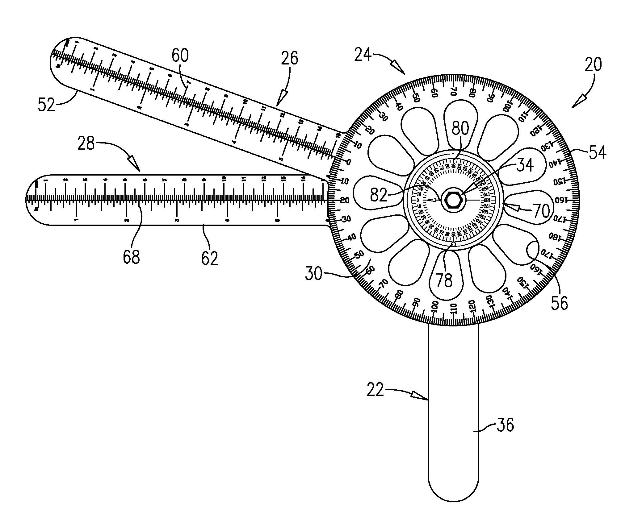
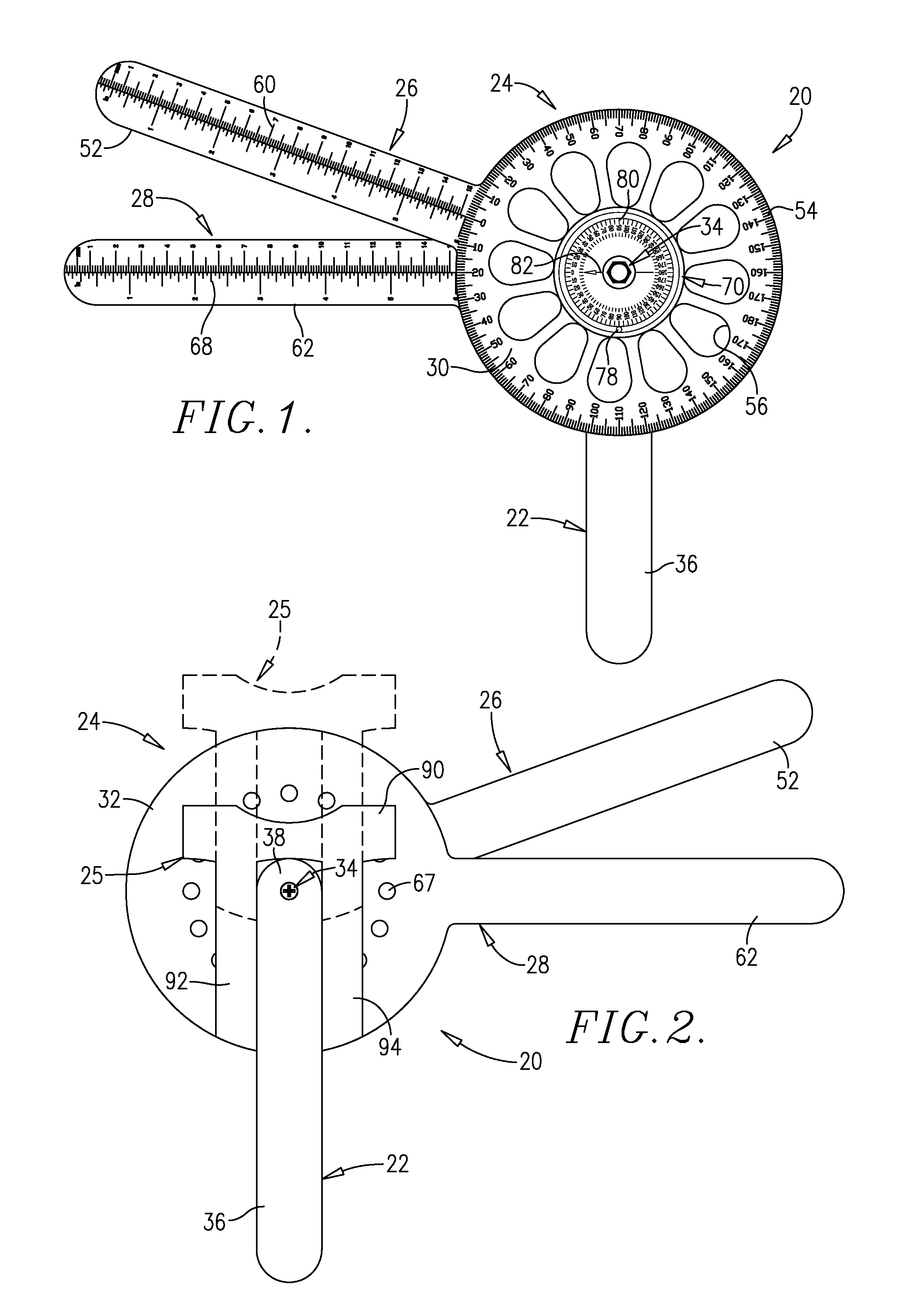
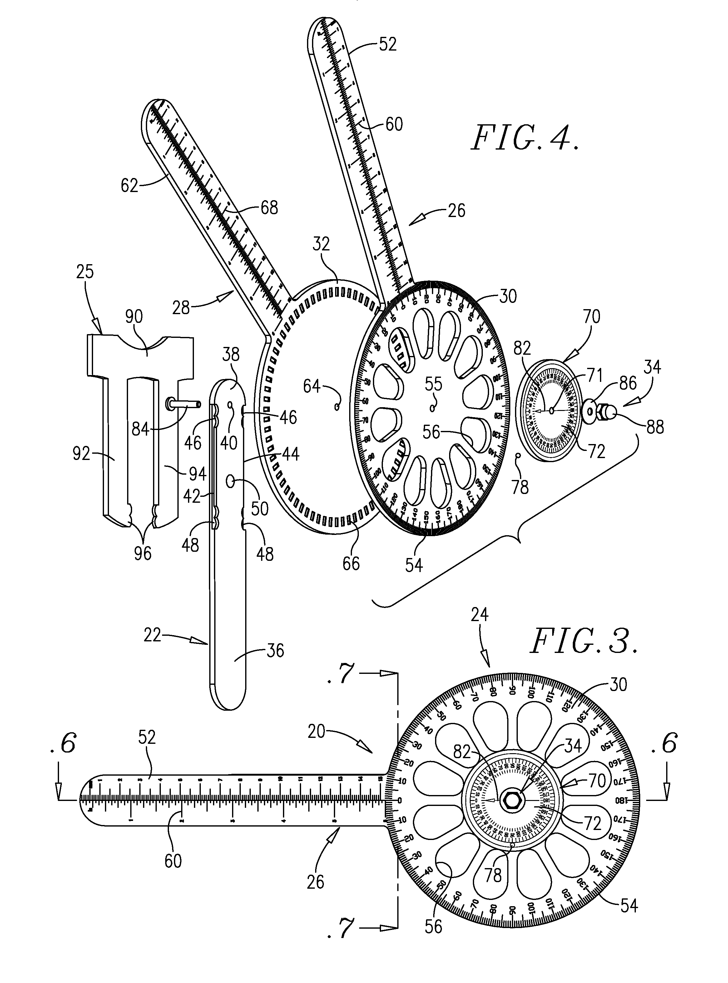
[0027]Turning now to the drawings, a preferred multiple-use goniometer 20 is illustrated in FIGS. 1 and 2 and broadly includes a handle 22 operatively coupled with and supporting an angle-indicating assembly 24, as well as a selectively useable auxiliary base 25. The assembly 24 includes a pair of elongated, angle-indicating, outer and inner arms 26 and 28, each supported by an enlarged, substantially circular, outer and inner base 30 and 32. The handle 22 and bases 30, 32 are interconnected by means of a pivot screw assembly 34. Goniometer 20 is designed to permit efficient range of motion measurements at various locations on a human patient.

[0028]In more detail, the handle 22 is formed of ridged synthetic resin material and has a lower grasping portion 36 and an upper connection portion 38. The later has a bore 40 as well as a pair of elongated, side marginal track recesses 42 and 44 terminating in upper and lower locking detents 46, 48 which are important for purposes to be descr...


PUM


Abstract

An improved, multiple-use range of motion goniometer (20) is provided having a handle (22) and an angle-indicating assembly (24) having a pair of angle-indicating arms (26, 28) supported by the handle (22). Preferably, the goniometer arms (26, 28) have corresponding circular bases (30, 32) which are coupled together via a pivot assembly (34). A secondary, gravity-operated, track and ball range of motion measurement device (70) is also secured to the bases (30, 32). An auxiliary base (25) secured to the handle (22) and is moveable between a recessed storage position and an extended use position. The outer base (30) is provided with thumb movement surfaces in the form of apertures (56), allowing the therapist holding the handle (22) to rotate the outer base (30) relative to the inner base (32) with one hand.

Description

BACKGROUND OF THE INVENTION[0001]1. Field of the Invention[0002]The present invention is broadly concerned with improved, multiple-use goniometers having a handle as well as a dual-arm angle indicating assembly which can be placed adjacent a patient's joint in order to provide range of motion measurements. The handle supports a pair of elongated angle-indicating arms which can be manipulated by a therapist using only one hand. The preferred goniometer also includes a secondary, gravity-operated, track and ball angle measuring device, as well as an auxiliary base.[0003]2. Description of the Prior Art[0004]Goniometers are instruments which measure the range or extent of movement of flexing joints such as the knee, ankle, wrist, shoulders, hips, and fingers. These devices are commonly used during the course of therapy after injuries or illnesses which affect joint movement, in order to provide an indicator of the extent of the patient's recovery. Generally available present-day goniome...

Claims


Application Information

Patent Timeline
Patent Type & Authority Applications(United States)
IPC IPC(8): G01B5/004
CPCA61B5/4528A61B5/1071
Inventor BRISCOE, LARRY G.MILLS, BRIAN S.
Owner QUANTUM TMT
Learn More