Moving mechanism, and compact camera, goniometer and fiberscope using the moving mechanism

a technology of moving mechanism and moving mechanism, which is applied in the direction of generator/motor, television system, instruments, etc., can solve the problems of difficult to provide the mechanical mechanism of the micro camera mounted in the mobile phone, the function cannot be satisfied, and the difficulty of applying this kind of voltage in the device such as the mobile phon

Inactive Publication Date: 2009-06-09
PANASONIC INTELLECTUAL PROPERTY CORP OF AMERICA
View PDF5 Cites 17 Cited by
  • Summary
  • Abstract
  • Description
  • Claims
  • Application Information

AI Technical Summary

Benefits of technology

[0011]It is an object of the present invention to provide a movement mechanism that is both easily miniaturized and can be driven by a small voltage, not for changing the shape of a lens, but for adjusting the distance between the lens, and an imaging element in order to focus a camera. Moreover, it is another object of the present invention to provide a miniature camera that uses the movement mechanism thereof.

Problems solved by technology

By comparison, it is difficult to provide micro cameras mounted in mobile phones with a mechanical mechanism so as to move the lens, due to space restraints.
Such a function cannot be satisfied by current wide angle lenses, and thus there is a need for a focusing mechanism for small cameras.
It is very difficult to apply this kind of voltage in a device such as a mobile phone.
However, in such methods it is difficult to control the shape of the lens accurately, and it is difficult to form clean images that have no distortion.
In order to take sharper images, it is necessary that the lens shape is a non-spherical hyperbolic curve-shape, but this is problematic in the method of Tokuhyo 2001-519539.

Method used


Image

  • Moving mechanism, and compact camera, goniometer and fiberscope using the moving mechanism
  • Moving mechanism, and compact camera, goniometer and fiberscope using the moving mechanism
  • Moving mechanism, and compact camera, goniometer and fiberscope using the moving mechanism

Examples


embodiment 1

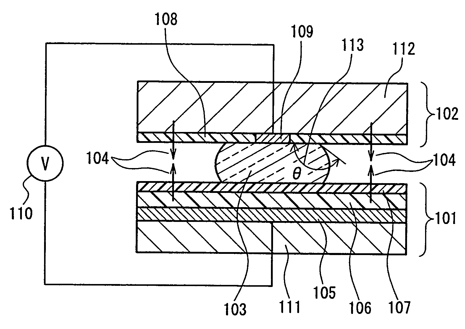
[0071]FIG. 12 is a schematic view showing a position movement mechanism of the present invention. A cross-sectional view of the vicinity of the first structural member 101, the liquid 103 and the second structural member 102 are shown in FIG. 1. In the present embodiment, the first structural member is one part of a bottom face of a fixed tube 404. The second structural member 102 is arranged such that it can move in the vertical direction within the tube. In the picture, gravity acts in the downward direction. Consequently, in the diagram, gravity is the binding force that acts on the second structural member 104.

[0072]The fixed tube 404 has a shape whose internal diameter is 10 mm and whose height is 30 mm, and its material is polycarbonate resin. The first structural member 101 is made from a silicon substrate 111 that has a thickness of 100 μm (see FIG. 1. In FIG. 12, this is included as a part of the first structural member 101), a platinum electrode 105 that has a thickness of...

embodiment 2

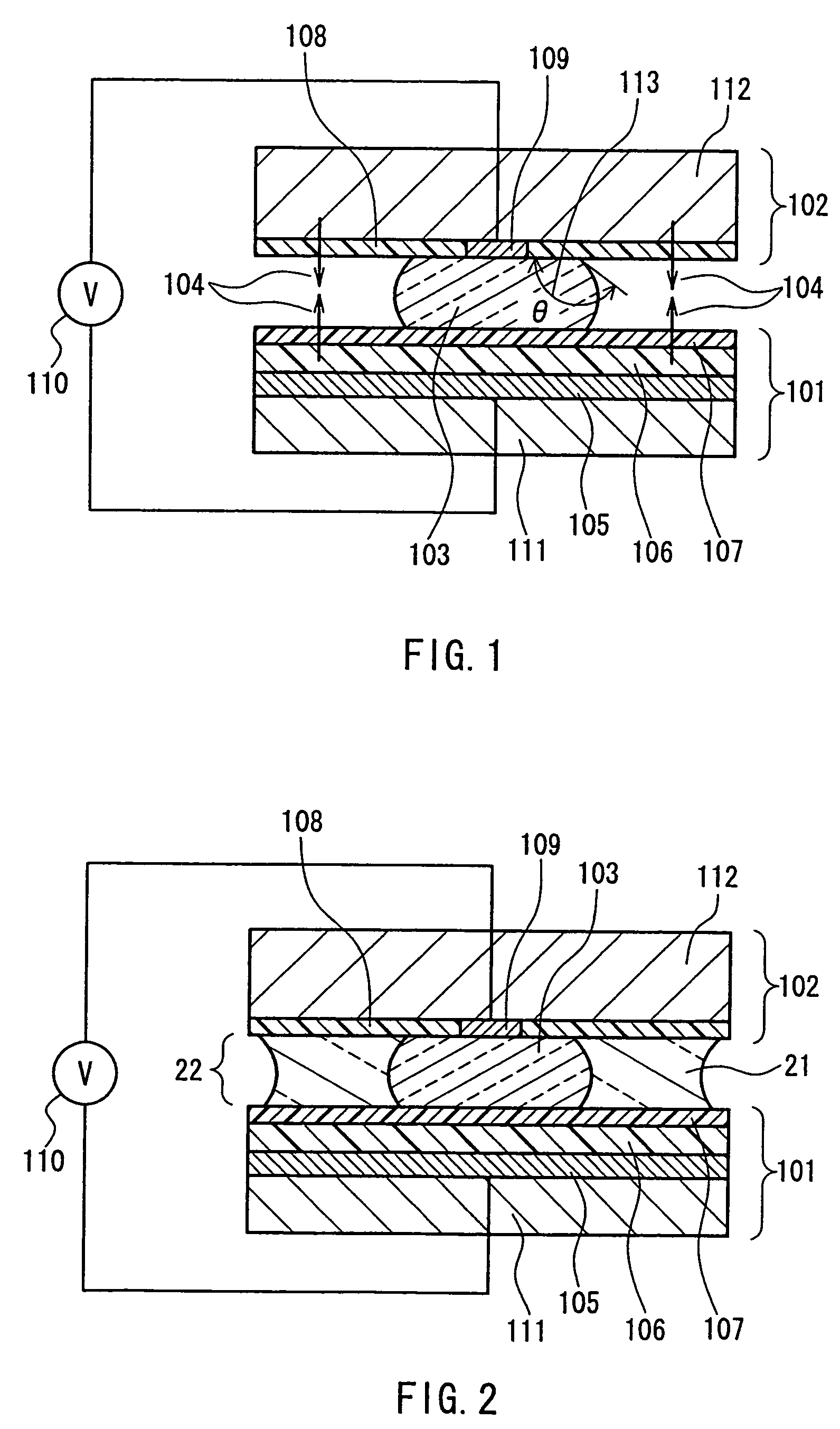
[0082]FIG. 13 is a schematic view showing a position movement mechanism of the present invention. FIG. 2 is a cross-sectional view of the vicinity of the first structural member 101, the liquid 103 and the second structural member 102. The basic structure of the present invention is the same as in Embodiment 1, however a filler liquid 21 has been added. Numeral 1001 is a fixed tube. In the present embodiment, a modified organic silicone oil (phenylmethylsiloxane homopolymer, manufactured by Gelest) with a specific gravity of 1.0 and a viscosity of 10 cPs is used as the filler liquid. The amount of filler liquid is adjusted such that the liquid 103 is completely enclosed within it, that no air bubbles are contained within it, and moreover, that it does not protrude from the gap between the first structural member and the second structural member. The surface tension of the filler liquid is on the order of 30 dyne / cm, and at the time of filling, the liquid surface has a concave shape....

embodiment 3

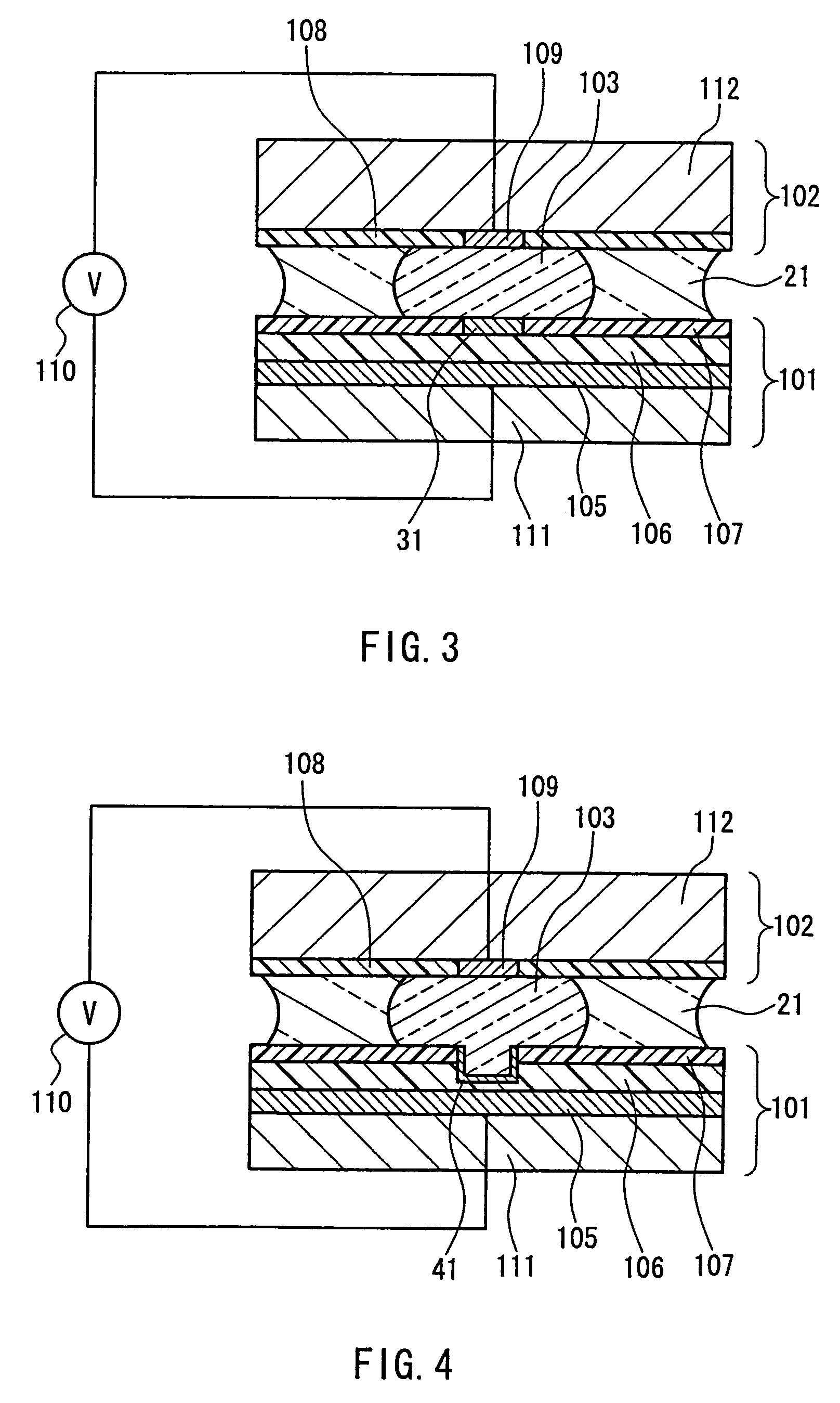
[0086]A position movement mechanism similar to that in Embodiment 2 was formed. However, a hydrophilic region exists on the insulating film of the first structural element wherein the water-repelling film is not formed, and the liquid is in contact with the hydrophilic region. A cross-sectional view of the vicinity of the first structural member, the liquid and the second structural member of the present embodiment is shown in FIG. 3. A circular hydrophilic region 31 with a diameter of 1 mm is formed in the center of the first structural member 101. After formation of the water-repelling film, the hydrophilic region is formed by affixing a metal mask that has circular holes of a diameter of 1 mm to the water-repelling film, and irradiating the metal mask with oxygen plasma. That is to say, the oxygen plasma only hits the water-repelling film in the part of the open holes, removing the water-repelling film, and the PZT is hydrophilically converted at the same time.

[0087]Because the l...


PUM


Abstract

The present invention provides a movement mechanism, in which a liquid arranged between a first structural member and a second structural member, wherein the interval between the first structural member and the second structural member is adjusted by changing the shape of the liquid due to an electro-wetting effect, by applying a voltage to the liquid. Accordingly, a position movement mechanism that is easily miniaturized and that can be driven with a low voltage can be provided, and moreover, a miniature camera, for example that uses the moving mechanism also can be provided. Furthermore, the movement mechanism also can be utilized as a position movement mechanism for micro-machines.

Description

FIELD OF THE INVENTION[0001]The present invention relates to position movement mechanisms that can be used in still cameras, video cameras and cameras for mobile phones, for example, and to compact cameras that use the movement mechanism.BACKGROUND OF THE INVENTION[0002]Still cameras, video cameras and cameras for mobile phones, for example, are designed to pass an image of an object to be photographed through a lens, to project it onto imaging elements such as solid-state imaging elements or charged coupled devices (CCD), or complementary metal-oxide semiconductor (CMOS) integrated circuits. In order to project a focused image onto the imaging elements, it is necessary to adjust the distance between the lens and the imaging element, in accordance with the distance between the lens and the object to be photographed.[0003]In still cameras and video cameras, in order to focus, the distance between the lens and the imaging element is adjusted by mechanically moving the lens using a sma...

Claims


Application Information

Patent Timeline
Patent Type & Authority Patents(United States)
IPC IPC(8): G02B13/16G02B1/06G02B3/14G02B26/02
CPCG02B3/14G02B26/005H02N11/006B81B3/0056
Inventor NAKAGAWA, TOHRU
Owner PANASONIC INTELLECTUAL PROPERTY CORP OF AMERICA
Why Eureka
Try Eureka