Methods and apparatus for drilling with casing

a technology of casing and drilling apparatus, applied in the direction of drilling pipes, drilling holes/well accessories, sealing/packing, etc., can solve the problem of limiting the hydrocarbon production ra

Active Publication Date: 2007-11-22
WEATHERFORD TECH HLDG LLC
View PDF101 Cites 67 Cited by
  • Summary
  • Abstract
  • Description
  • Claims
  • Application Information

AI Technical Summary

Problems solved by technology

Also, the smaller casing at the bottom of the hole may limit the hydrocarbon production rate.

Method used


Image

  • Methods and apparatus for drilling with casing
  • Methods and apparatus for drilling with casing
  • Methods and apparatus for drilling with casing

Examples


Embodiment Construction

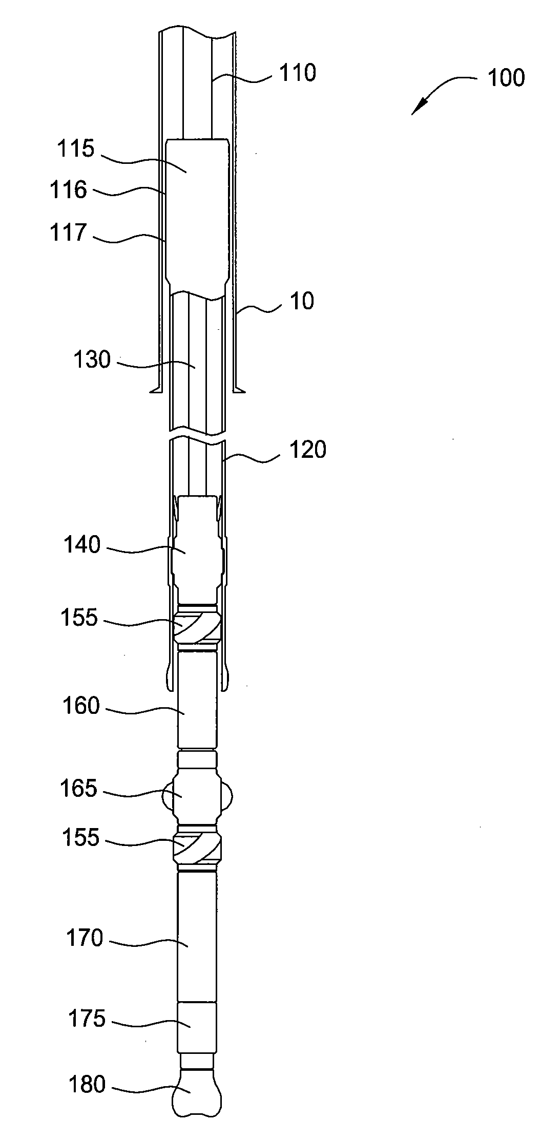
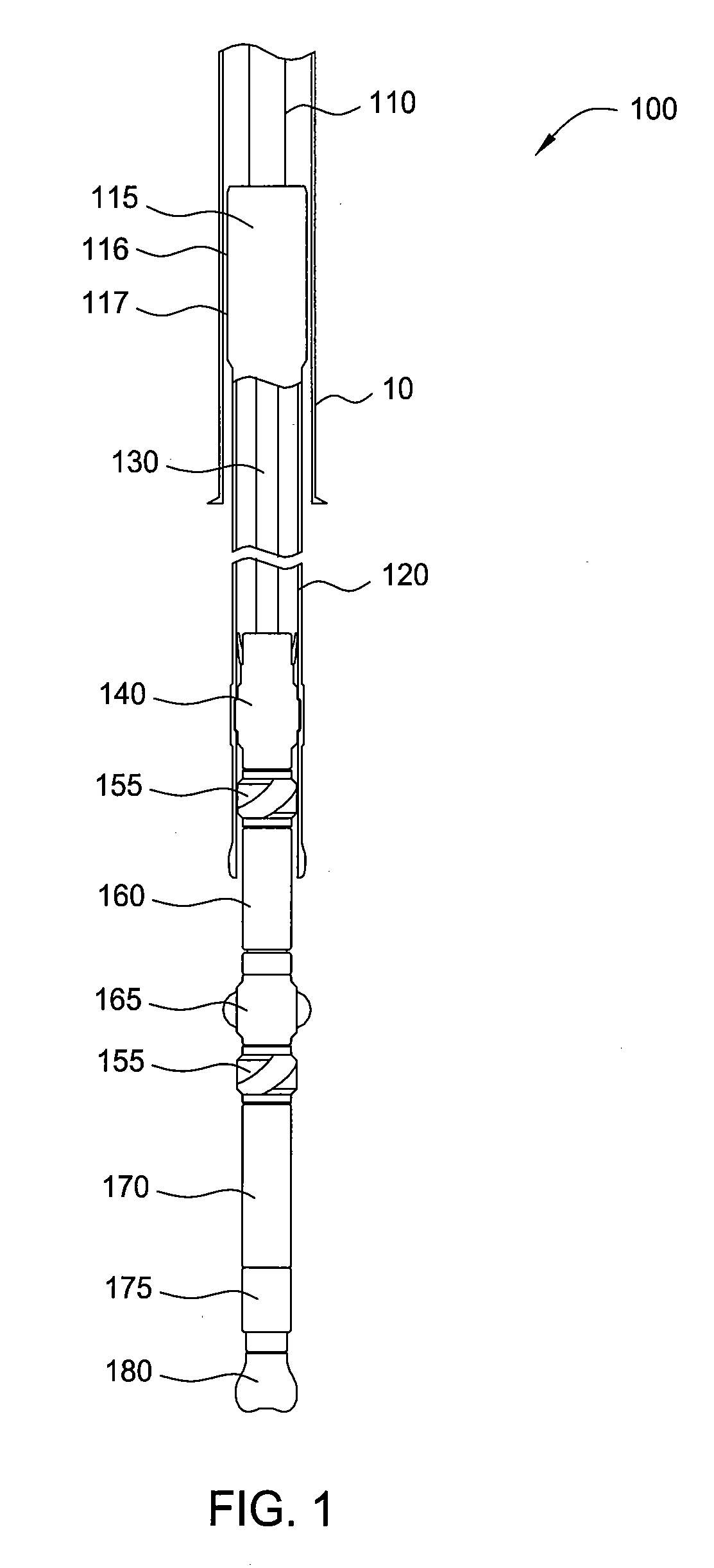
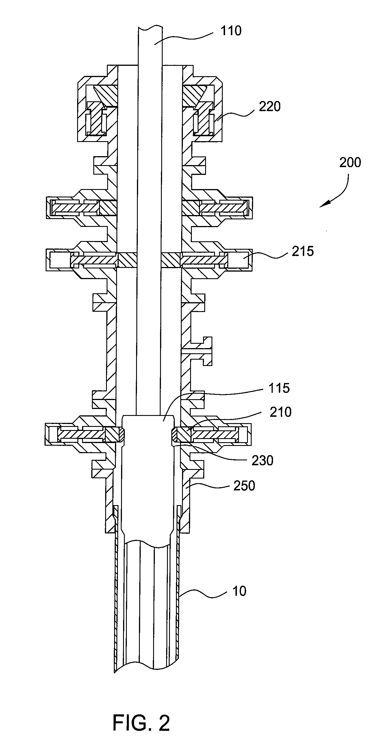
[0020] In one embodiment, a drilling apparatus includes a liner as a portion of the drill string. The axial and torsional loads are carried by the drill pipe and then transferred to the drilling liner by the use of a liner drilling tool. The forces are then transmitted along the liner to a latch. The loads are then transferred from the liner to the latch and attached BHA. The drilling apparatus may include an inner string that connects the liner drilling tool at the liner top to the BHA. This way, when the liner drilling tool and latch are disconnected from the liner, the drill pipe can pull the inner string and BHA from the liner and bore hole. In one embodiment, releasing and pulling the liner drilling tool also releases and pulls the BHA out of hole with the inner string. The inner string can also act as a conduit for fluid flow from the drill pipe to the BHA below. It should be noted that the fluid flow could be split between the inner string and the liner ID, or the fluid flow ...


PUM


Abstract

In one embodiment, a method of forming a wellbore includes running a liner drilling assembly into the wellbore, the liner drilling assembly having a liner, a conveying member, one or more connection members, and a drilling member. The method includes temporarily suspending the liner at a location below the rig floor; releasing the conveying member and the drilling member from the liner; re-connecting the conveying member to the liner; releasing the liner from its location of temporary suspension; and advancing the liner drilling assembly.

Description

CROSS-REFERENCE TO RELATED APPLICATION [0001] This application claims benefit of U.S. Provisional Patent Application No. 60 / 747,929, filed on May 22, 2006, which application is incorporated herein by reference in its entirety.BACKGROUND OF THE INVENTION [0002] 1. Field of the Invention [0003] The present invention relates apparatus and methods for drilling and completing a wellbore. Particularly, the present invention relates to apparatus and methods for forming a wellbore, lining a wellbore, and circulating fluids in the wellbore. The present invention also relates to apparatus and methods for cementing a wellbore. [0004] 2. Description of the Related Art [0005] In the drilling of oil and gas wells, a wellbore is formed using a drill bit that is urged downwardly at a lower end of a drill string. After drilling a predetermined depth, the drill string and bit are removed, and the wellbore is lined with a string of casing. An annular area is thus defined between the outside of the cas...

Claims


Application Information

Patent Timeline
Patent Type & Authority Applications(United States)
IPC IPC(8): E21B7/00
CPCE21B7/20E21B43/10E21B33/06E21B7/208E21B10/26E21B17/07
Inventor GIROUX, RICHARD L.ODELL, ALBERT C. IIXU, WEI
Owner WEATHERFORD TECH HLDG LLC
Why Eureka
Try Eureka