

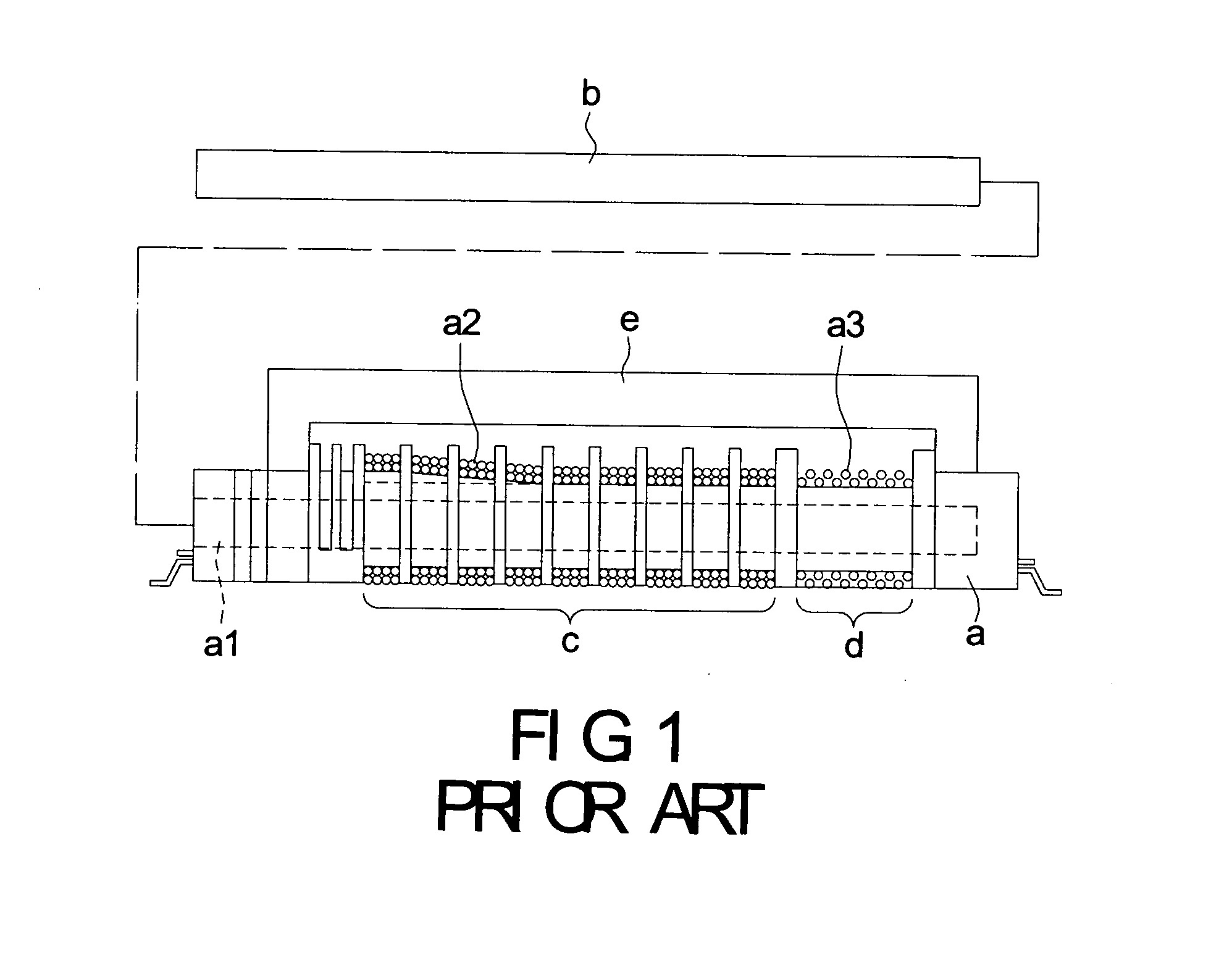
High voltage transformer for controlling inductance leakage
a high-voltage transformer and inductance technology, which is applied in the direction of transformer/inductance details, basic electric elements, inductances, etc., can solve the problems of reducing the efficiency of the magnetic unit, the switching loss caused by switching the transformer between high voltage and low voltage cannot be well controlled, and the magnetic flux of the transformer is too high, etc., to achieve enhanced inductance leakage of the transformer
- Summary
- Abstract
- Description
- Claims
- Application Information
AI Technical Summary
Benefits of technology
Problems solved by technology
Method used
Image

Examples
second embodiment
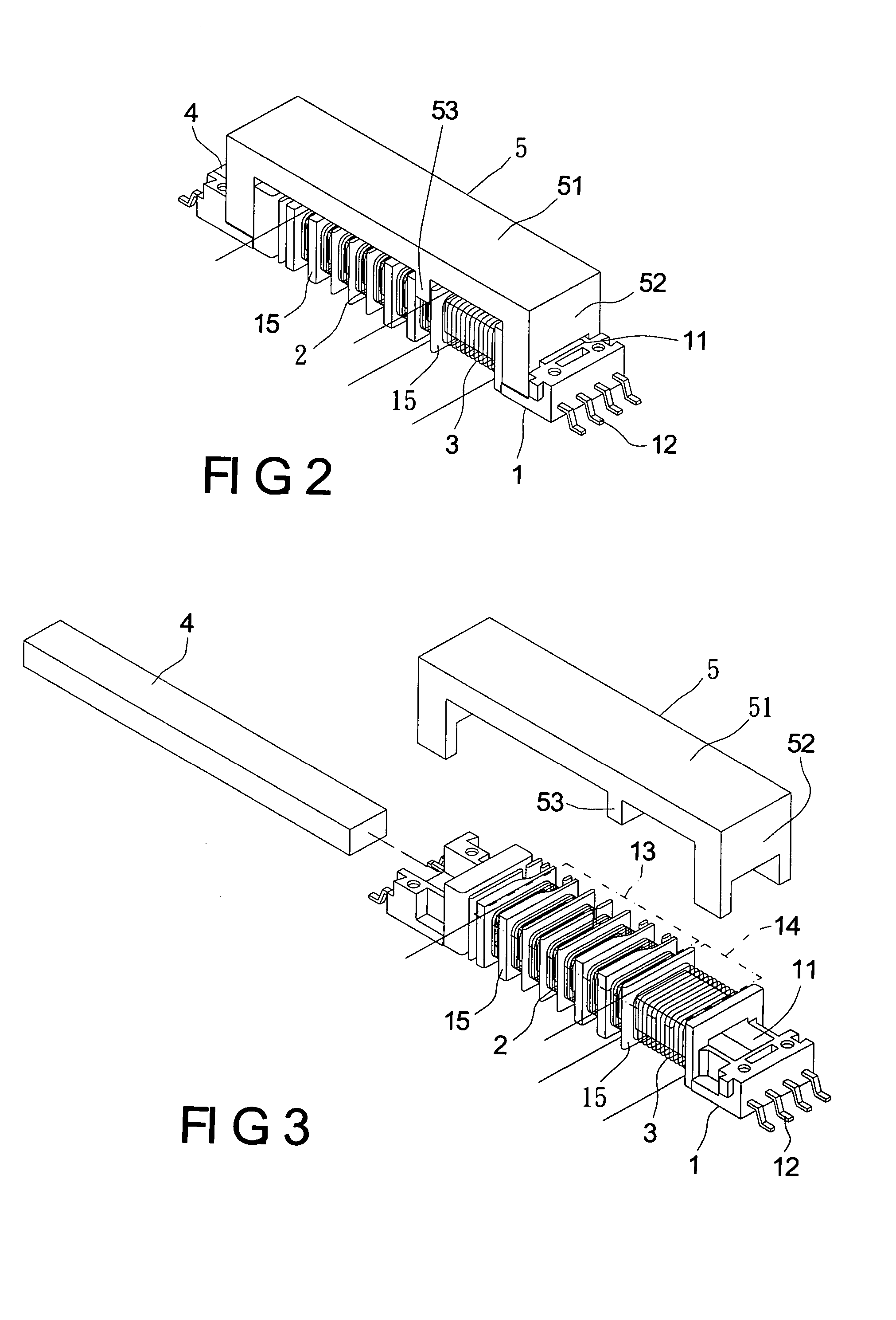
[0031]FIG. 6 shows a perspective view of the transformer of the present invention. The distance of the slot-shaped space on the wire frame formed by two specified adjacent blocking walls 15 is greater than the transverse beam 53. Therefore, the transverse beam 53 can be moved in the slot-shaped space.
third embodiment
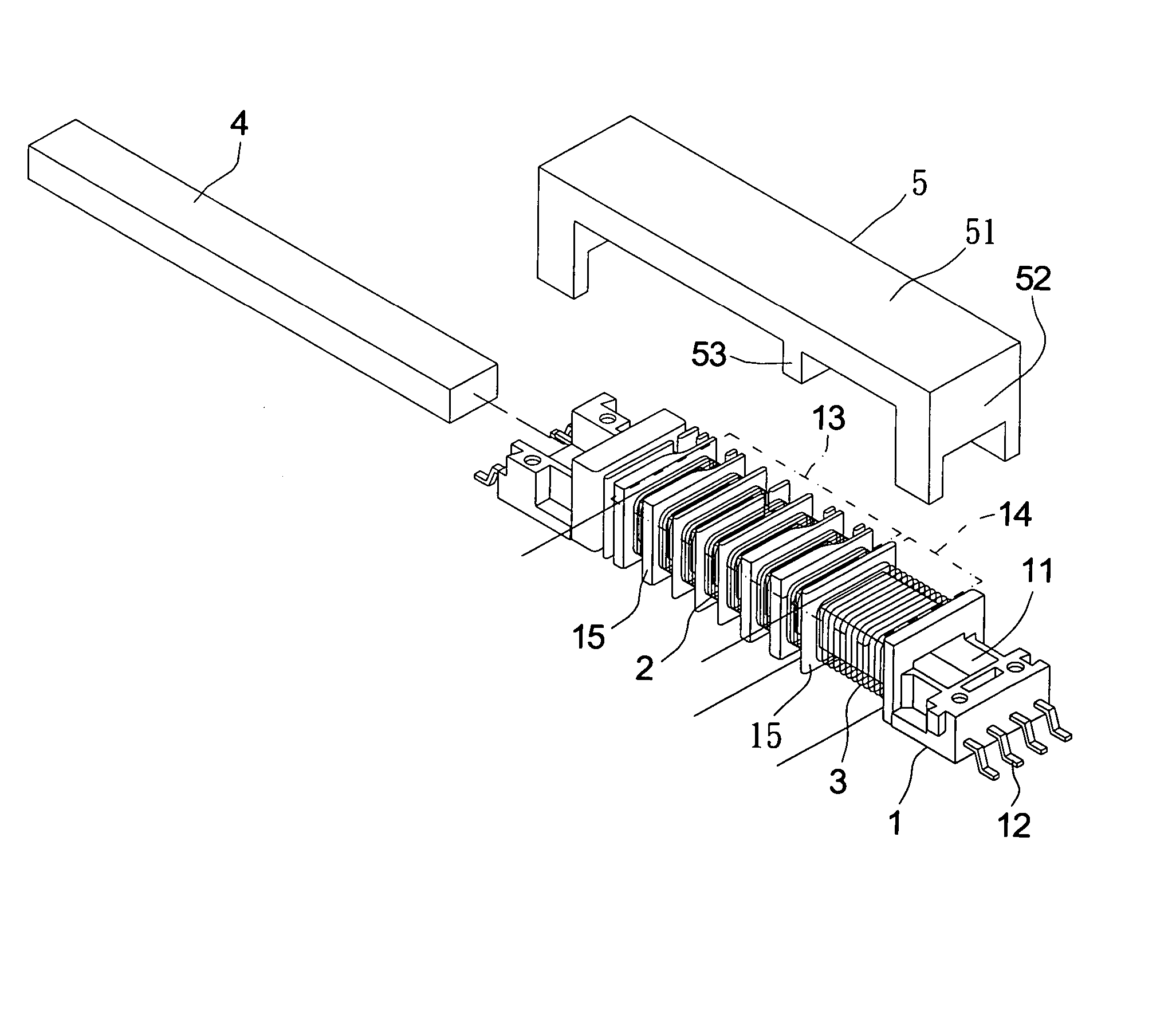
[0032] Reference is made to FIGS. 7 and 8, which show a perspective view of the transformer of the present invention. The high voltage transformer for controlling inductance leakage includes two wire frames 1, two first windings 2, two second windings 3, two first magnetic units 4, and a second magnetic unit 5. Two linking element sets 16 are located at the side of the wire frame 1. The linking element set 16 is composed of at least one tenon 161 located at one side of the wire frame 1 and a concave slot 162 located at another side of the wire frame 1. By assembling the tenon 161 and the concave slot 162 located on the two sides of the one wire frame 1 with the tenon 161 and the concave slot 162 of another adjacent wire frame 1, the two wire frames 1 are assembled with each other and there is an appropriate gap between the two wire frames 1.
[0033] Each of the first windings 2 is wound at a slot-shaped space formed by the blocking walls 15 located at the first region 13 on the corres...
fourth embodiment
[0038]FIG. 9 shows a perspective view of the transformer of the present invention. Each of the two first magnetic units 4 is plugged into the receiving space 11 of the wire frame 1 from one end of the corresponding wire frame 1. The first magnetic unit 4 is a beam body 41. A plurality of plugging rods extends from one side of the beam body 41. Each of the plugging rods is plugged into the receiving space 11 of each wire frame 1. Changing the shape of the first magnetic unit 4 makes the primary side winding region formed by the two first windings 2 separate from the secondary side winding region formed by the two second windings 3 so as to form the magnetic flux path.
[0039] The present invention has the following characteristics:
[0040] 1. The present invention separates the primary side winding region from the secondary side winding region via the transverse beam 53 of the magnetic unit located on the outside of the wire frame 1 so as to control the switching loss caused by switchin...
PUM
 Abstract
Description
Claims
Application Information