Direct Current Control with Low E-M Emission
a technology of direct current supply and low e-m emission, which is applied in the direction of pulse technique, dc-dc conversion, power conversion system, etc., can solve the problems of increased electromagnetic emissions, substantial heat, damage to the circuit,
- Summary
- Abstract
- Description
- Claims
- Application Information
AI Technical Summary
Benefits of technology
Problems solved by technology
Method used
Image
Examples
example 1
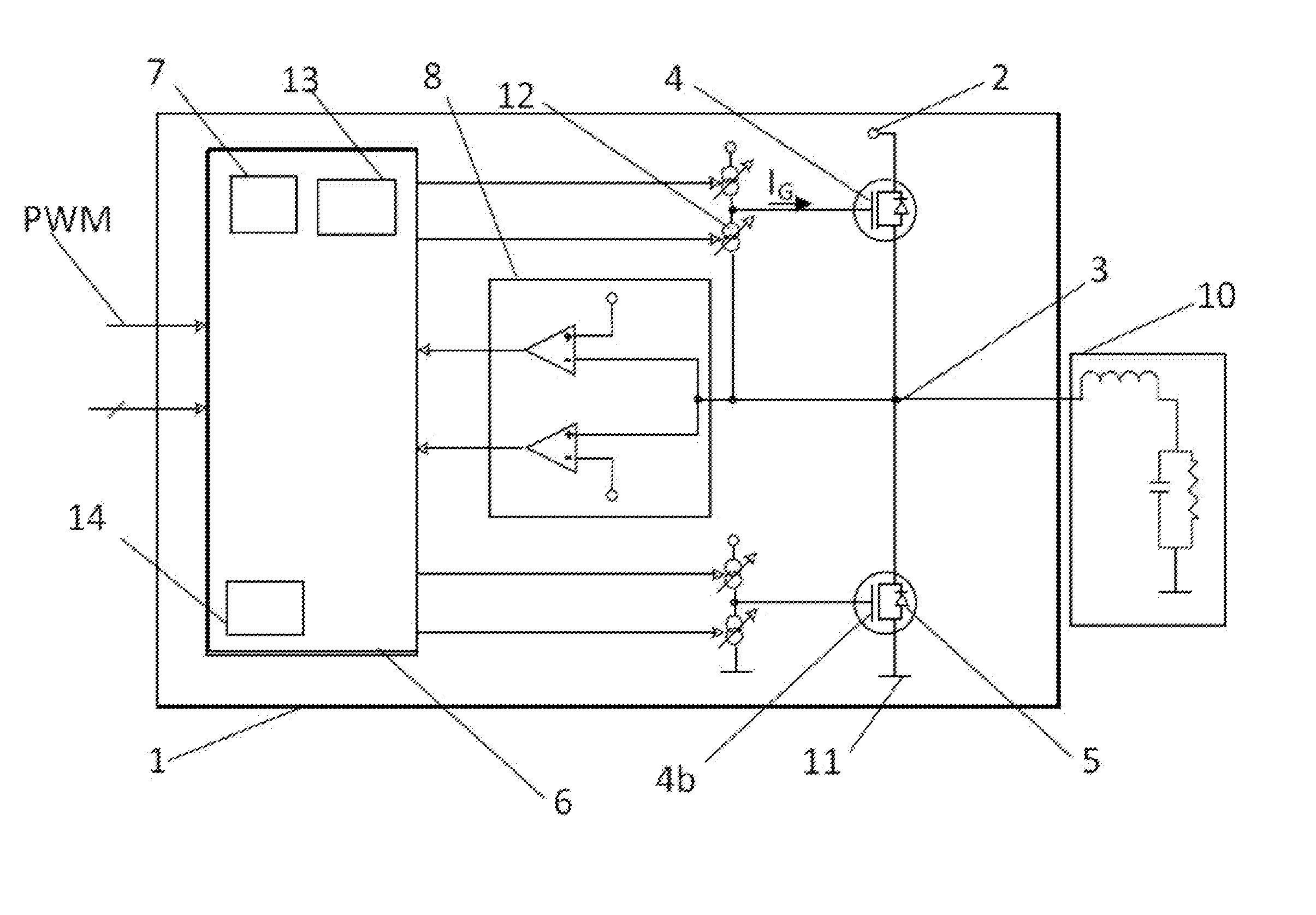
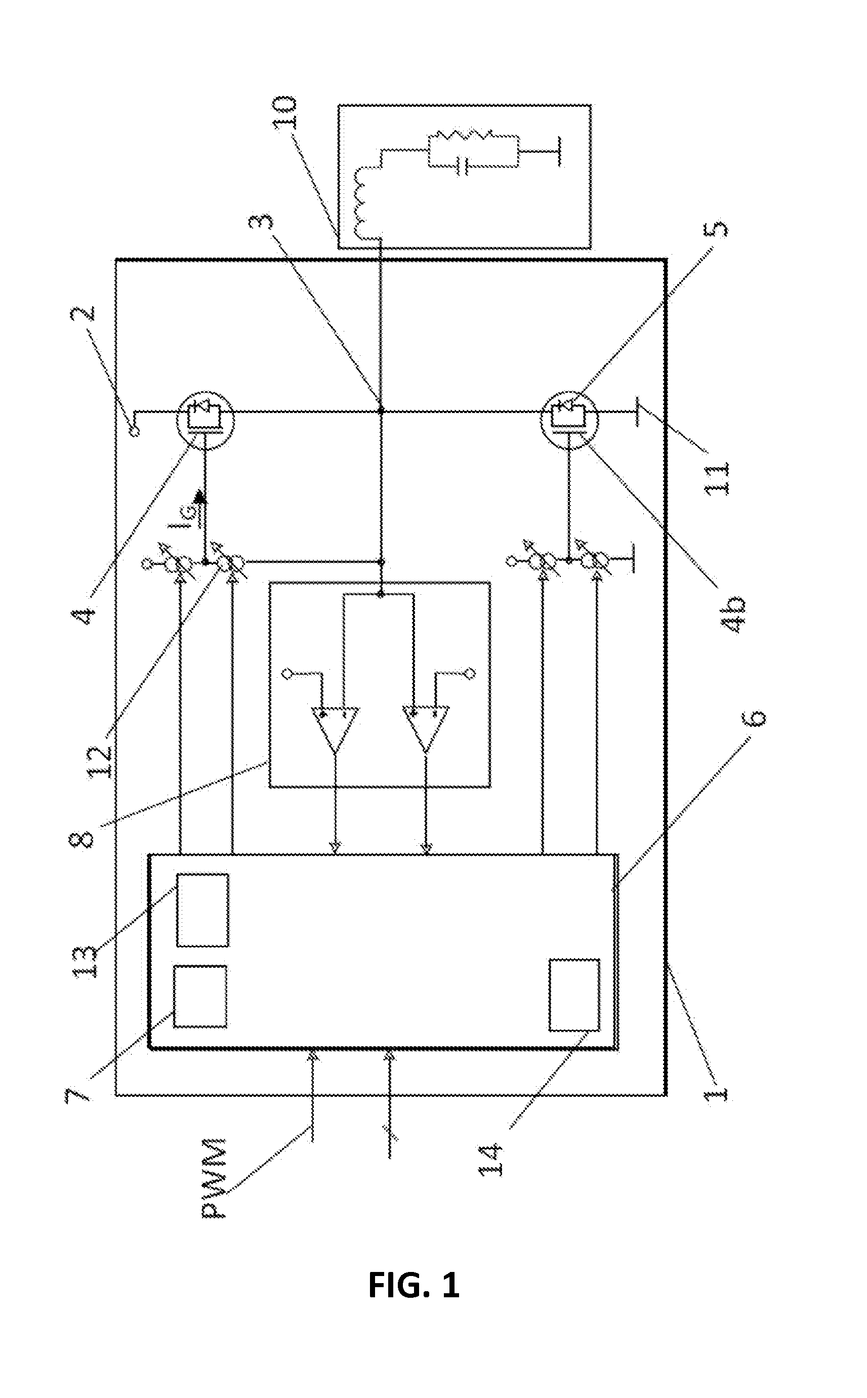
[0087]After a falling PWM input at TO and if the assumed current direction through the load is positive (CDI=1)
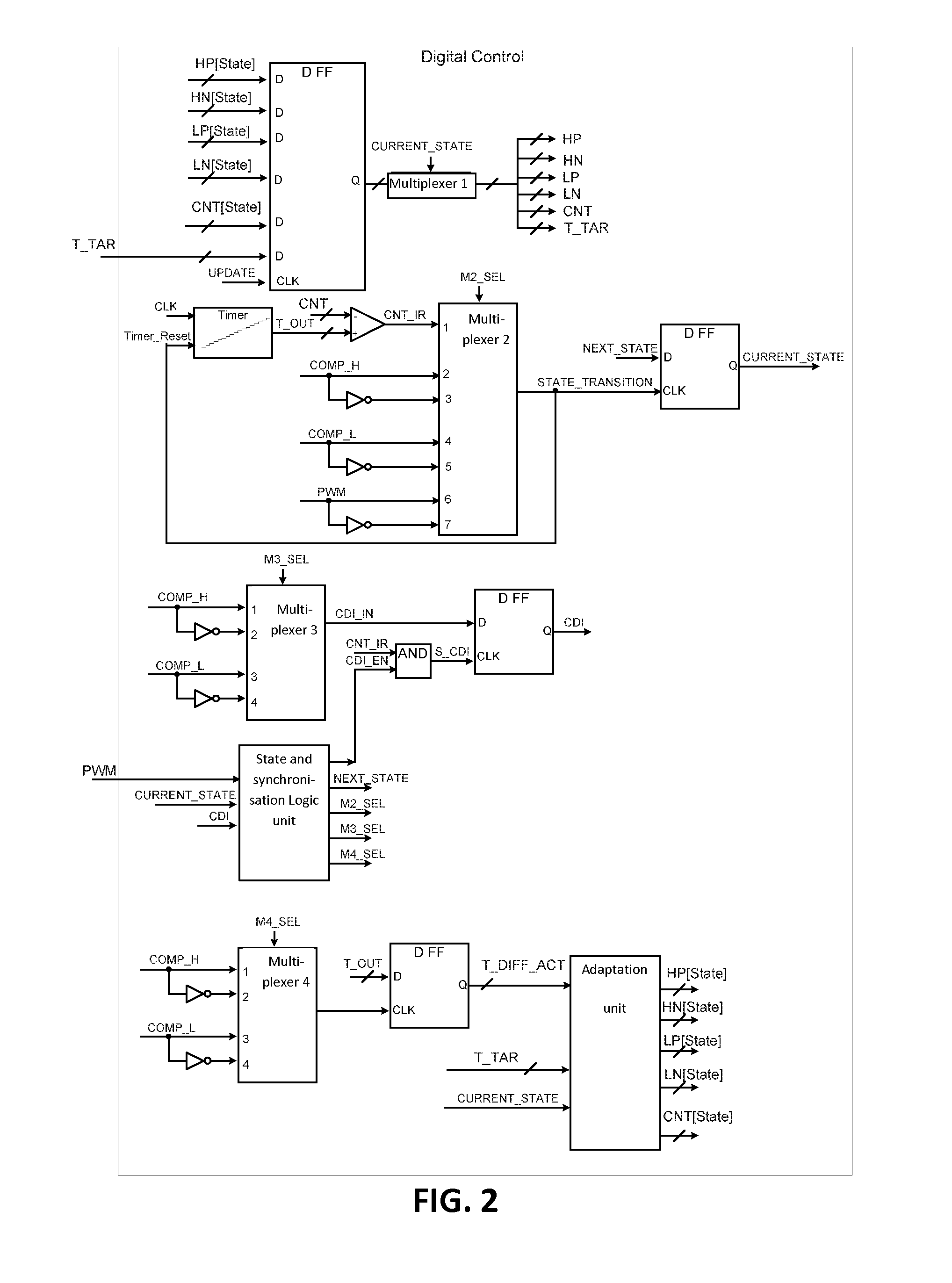
[0088]First the control gate of the HS FET is discharged with a discharge current strength HN[1] for a period of time CNT[1] and then it is reduced the discharge current to a lower value HN[2]. CNT[1] and HN[1] can either be predetermined or adapted parameters from a previous cycle in a way, that T1 occurs a desired target period of time T_TAR[2] before the terminal load voltage falls below a first reference voltage VERF_H. T_TAR[2] may be chosen to compensate any delay caused by the comparator and logic, in a way that the load voltage has not significantly changed before T1.
[0089]Taking a measure (TCF1) of the time difference between T1 and the instance in time when the terminal load voltage falls below a first reference voltage VERF_H during the current cycle and adapting parameter table entries CNT[1] and / or HN[1], so that T1 occurs a certain time prior to the terminal l...
example 2
[0103]After receiving a rising edge on the PWM input at time TR0 and if the assumed current direction thru the load is positive (CDI=1).
[0104]Discharging the gate of the LS FET with a discharge current strength LN[8] for a period of time CNT[8] and reducing the discharge current strength after the period of time at TR1. CNT[8] a predetermined or adapted parameter so that the discharge current is reduced before the current commutation from the LST to the LSD begins (change of diode voltage).
[0105]The duration CNT[8] and current strength LN[8] may be either predetermined or being adapted.
[0106]CNT[8] maybe calculated as
CNT[8]=Constant5*(CNT[1]*HN[1] / LN[8])
[0107]At TR1 discharging the gate of the LS FET with a discharge current strength LN[9] for a period of time CNT[9] and increasing the discharge current strength after the period of time at TR2. CNT[9] and LN[9] being either predetermined or being adapted parameter chosen in order that the current commutation from LST to LSD is compl...
example 3
[0125]After a falling PWM input at TF0 and if the assumed current direction thru the load is negative (CDI=0):
[0126]Discharging the gate of the HS FET with a discharge current strength HN[20] for a period of time CNT[20] and then to reduce the discharge current to a lower value HN[21].
[0127]CNT[20] a predetermined or adapted parameter so that the discharge current is reduced before the current commutation from the HST to the HSD begins (change of diode voltage).
[0128]CNT[20] maybe calculated as
CNT[20]=Constant20*(CNT[30]*LN[30] / HN[20])
[0129]At TF1 discharging the gate of the HS FET with a discharge current strength HN[21] for a period of time CNT[21] and increasing the discharge current strength after the period of time at TF2. CNT[21] and HN[21] being either predetermined or being adapted parameter chosen in order that the current commutation from LST to LSD is completed before TF2.
[0130]CNT[21] may be a function of CNT[30]:
CNT[21]=Constant21A−Constant21B*CNT[30]
[0131]CNT[22] and H...
PUM
 Abstract
Description
Claims
Application Information
 - R&D
- Intellectual Property
- Life Sciences
- Materials
- Tech Scout
- Unparalleled Data Quality
- Higher Quality Content
- 60% Fewer Hallucinations
Browse by: Latest US Patents, China's latest patents, Technical Efficacy Thesaurus, Application Domain, Technology Topic, Popular Technical Reports.
© 2025 PatSnap. All rights reserved.Legal|Privacy policy|Modern Slavery Act Transparency Statement|Sitemap|About US| Contact US: help@patsnap.com


