Control device for electric motor driving apparatus

a technology for driving apparatuses and control devices, applied in the direction of motor/generator/converter stoppers, dynamo-electric gear control, dynamo-electric converter control, etc., can solve the problems of limited rectangular wave control, limited opportunities to execute low-switching loss rectangular wave control, and torque rippl

Active Publication Date: 2014-01-07
AISIN AW CO LTD
View PDF9 Cites 2 Cited by
  • Summary
  • Abstract
  • Description
  • Claims
  • Application Information

AI Technical Summary

Benefits of technology

[0005]Incidentally, with rectangular wave control, the number of times a switching element constituting the inverter is switched ON / OFF can be reduced greatly in comparison with PWM control, and therefore switching loss can be suppressed. Hence, rectangular wave control may be performed from a lower rotation speed region in order to improve the efficiency of the electric motor driving apparatus. However, when the system voltage is boosted during execution of the rectangular wave control, a balance between the voltages supplied to the coils of the respective phases may be disrupted, causing a torque ripple in which the output torque of the alternating current electric motor varies in accordance with a rotation angle. With the constitution described in JP-A-2006-311770, the system voltage is boosted during PWM control and the rectangular wave control is performed after the system voltage has become equal to the maximum system voltage achieved by boosting the power supply voltage. Therefore, the rectangular wave control is not performed until the system voltage is boosted to the maximum system voltage, and as a result, a usage region of the low-switching loss rectangular wave control is limited to a high rotation speed region.
[0006]Variation in the system voltage also occurs under operating conditions or in a system where the direct current voltage is supplied as is from the direct current power supply without actively modifying the system voltage using a boost converter. In other words, the output voltage of the direct current power supply varies in accordance with a discharge current or a charging current of the direct current power supply, and the system voltage varies in accordance therewith. If rectangular wave control is not performed during variation of the system voltage, the occurrence of a torque ripple caused by the rectangular wave control can be prevented, but opportunities to execute the low-switching loss rectangular wave control are limited. If rectangular wave control is performed during variation of the system voltage, on the other hand, the low-switching loss rectangular wave control can be executed, but a torque ripple is likely to occur due to the rectangular wave control.
[0007]The present invention has been designed in consideration of the problems described above, and an object thereof is to provide a control device for an electric motor driving apparatus which can expand a usage region of rectangular wave control, in which little switching loss occurs, to a low rotation speed region side and suppress vibration in an alternating current electric motor even when a system voltage varies during the rectangular wave control.

Problems solved by technology

However, when the system voltage is boosted during execution of the rectangular wave control, a balance between the voltages supplied to the coils of the respective phases may be disrupted, causing a torque ripple in which the output torque of the alternating current electric motor varies in accordance with a rotation angle.
Therefore, the rectangular wave control is not performed until the system voltage is boosted to the maximum system voltage, and as a result, a usage region of the low-switching loss rectangular wave control is limited to a high rotation speed region.
If rectangular wave control is not performed during variation of the system voltage, the occurrence of a torque ripple caused by the rectangular wave control can be prevented, but opportunities to execute the low-switching loss rectangular wave control are limited.
If rectangular wave control is performed during variation of the system voltage, on the other hand, the low-switching loss rectangular wave control can be executed, but a torque ripple is likely to occur due to the rectangular wave control.

Method used


Image

  • Control device for electric motor driving apparatus
  • Control device for electric motor driving apparatus
  • Control device for electric motor driving apparatus

Examples


first embodiment

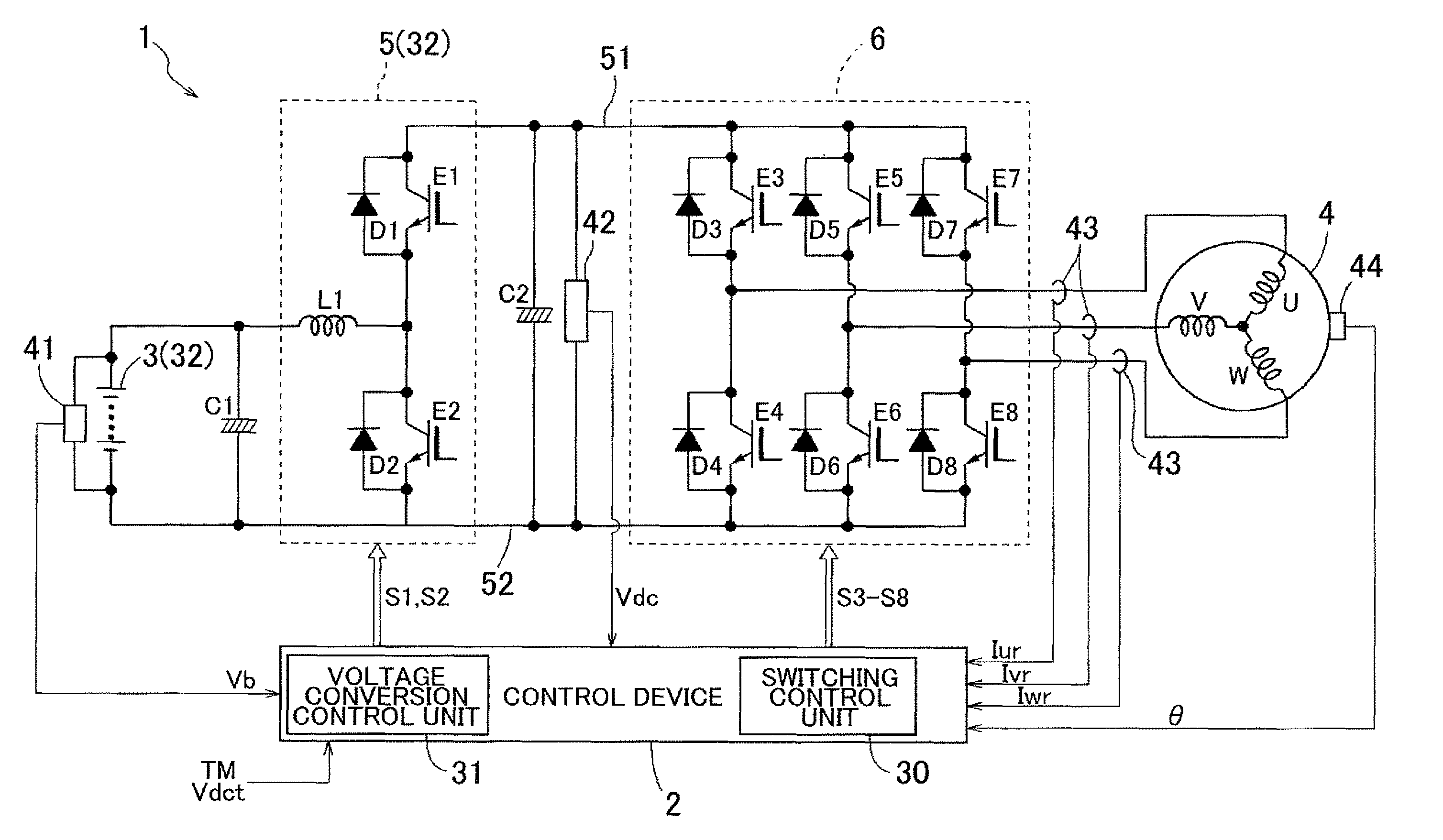
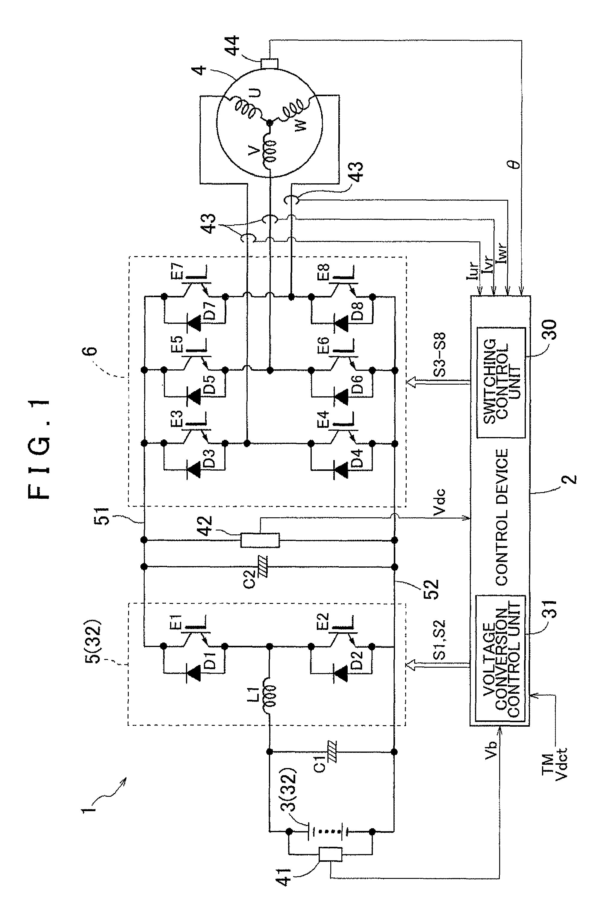
[0031]A first embodiment of the present invention will now be described on the basis of the drawings. As shown in FIG. 1, in this embodiment, an example in which an electric motor driving apparatus 1 is constituted by an apparatus for driving a synchronous electric motor 4 having an embedded magnet structure (an IPMSM; to be referred to simply as the “electric motor 4” hereafter), which serves as an alternating current electric motor operated by a three-phase alternating current, will be described. The electric motor 4 also operates as a power generator as required, and is used as a drive power source for an electric vehicle, a hybrid vehicle, or similar, for example. The electric motor driving apparatus 1 includes a system voltage generation unit 32 for generating a direct-current system voltage, and an inverter 6 for converting the system voltage Vdc into an alternating current voltage having three mutually deviating phases and supplying the alternating current voltage to the elec...

second embodiment

[0079]Next, a second embodiment of the present invention will be described. In the first embodiment, an example in which the system voltage generation unit 32 includes the converter 5 was described, but in this embodiment, as shown in FIG. 9, the system voltage generation unit 32 includes only the direct current power supply 3 and not the converter 5. Hence, in this embodiment, the inverter 6 is connected to the direct current power supply 3 without passing through the converter 5, and as a result, the system voltage Vdc corresponds to the output voltage of the direct current power supply 3. Further, the control device 2 includes the switching control unit 30 but not the voltage conversion control unit 31 of the first embodiment. The switching control unit 30 differs from that of the first embodiment in that it executes the rectangular wave width adjustment control without cooperating with the voltage conversion control unit 31. Moreover, the rate of change K of the system voltage V...


PUM


Abstract

A control device for an electric motor driving apparatus, configured with a switching control unit that performs rectangular wave control in which a plurality of switching elements provided in a direct current-alternating current conversion unit are ON / OFF-controlled to output rectangular wave-shaped voltages of a plurality of phases. System voltage varies during execution of the rectangular wave control, the switching control unit performs rectangular wave width adjustment control to set ON / OFF timings of the plurality of switching elements on the basis of a rate of change of the system voltage such that time-integrated values of the rectangular wave-shaped voltages of the respective phases within a control period set at a length corresponding to an integral multiple of a single electrical angle period are substantially identical among the respective phases.

Description

INCORPORATION BY REFERENCE[0001]The disclosure of Japanese Patent Application No. 2009-147830 filed on Jun. 22, 2009 including the specification, drawings and abstract is incorporated herein by reference in its entirety.BACKGROUND OF THE INVENTION[0002]The present invention relates to a control device for controlling an electric motor driving apparatus that includes a system voltage generation unit for generating a direct-current system voltage, and a direct current-alternating current conversion unit for converting the system voltage into an alternating current voltage having a plurality of mutually deviating phases and supplying the alternating current voltage to an alternating current electric motor.DESCRIPTION OF THE RELATED ART[0003]A typically used electric motor driving apparatus drives an alternating current electric motor by converting a direct current voltage from a direct current power supply into an alternating current voltage using an inverter. In this type of electric ...

Claims


Application Information

Patent Timeline
Patent Type & Authority Patents(United States)
IPC IPC(8): H02P1/04H02P6/06H02P6/08H02P6/28H02P21/00H02P21/05H02P21/22H02P23/04H02P25/026H02P27/06H02P27/08
CPCH02P6/10
Inventor IWATSUKI, KENCHEN, ZHIQIAN
Owner AISIN AW CO LTD
Why Eureka
Try Eureka