Refractive compact range

a compact range and refractive technology, applied in the direction of antenna radiation diagrams, instruments, antennas, etc., can solve the problems of limiting the field of regard for the sensor, requiring a large interior space, and requiring a large quantity of radar-absorbing materials, so as to reduce the destructive diffractive interference pattern

Active Publication Date: 2007-11-22
RAYTHEON CO
View PDF9 Cites 14 Cited by
  • Summary
  • Abstract
  • Description
  • Claims
  • Application Information

AI Technical Summary

Benefits of technology

[0010]According to yet another aspect of the invention, a radio frequency test range includes: a physical space that includes a source zone for placing an antenna, and a test zone for placing a device to be tested; a lens between the source zone and the test zone; and an apodizer placed between the source zone and the test zone. The lens collimates the energy emitted by the antenna or other source onto the test zone. The apodizer greatly reduces destructive diffractive interference patterns from re

Problems solved by technology

However, testing outdoors or in a large building under controlled conditions is often impractical and/or expensive, and thus smaller indoor test ranges are often desired and used for testing.
Such a direct illumination test facility has the disadvantage of requiring a large interior space, as well as a significant quantity of radar-absorbing material.
However, such indoor test ranges have a limited field of regard (nominally about seven to ten degrees) which limits the field of regard for the se

Method used


Image

  • Refractive compact range
  • Refractive compact range
  • Refractive compact range

Examples


Embodiment Construction

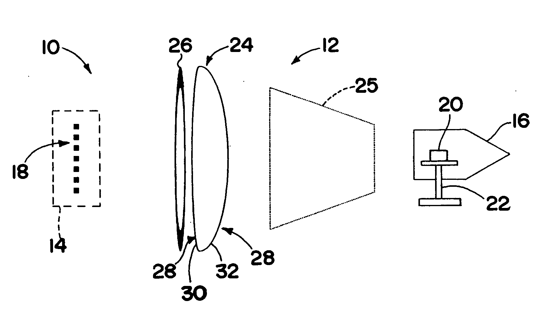
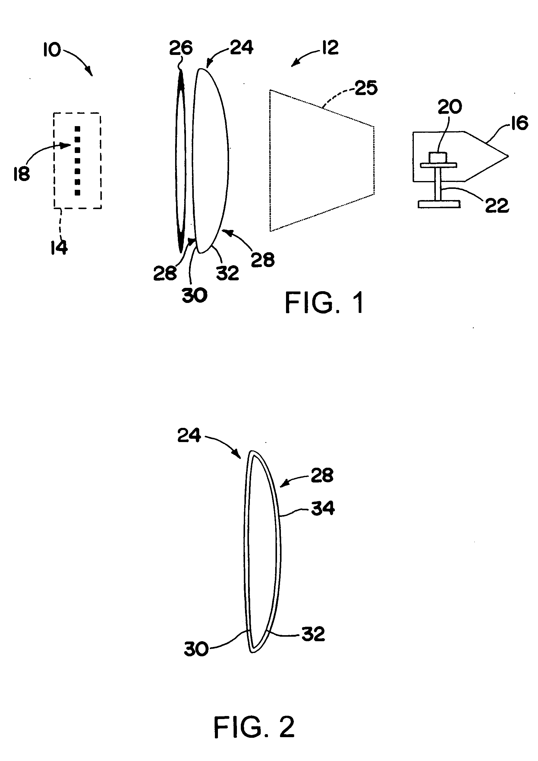
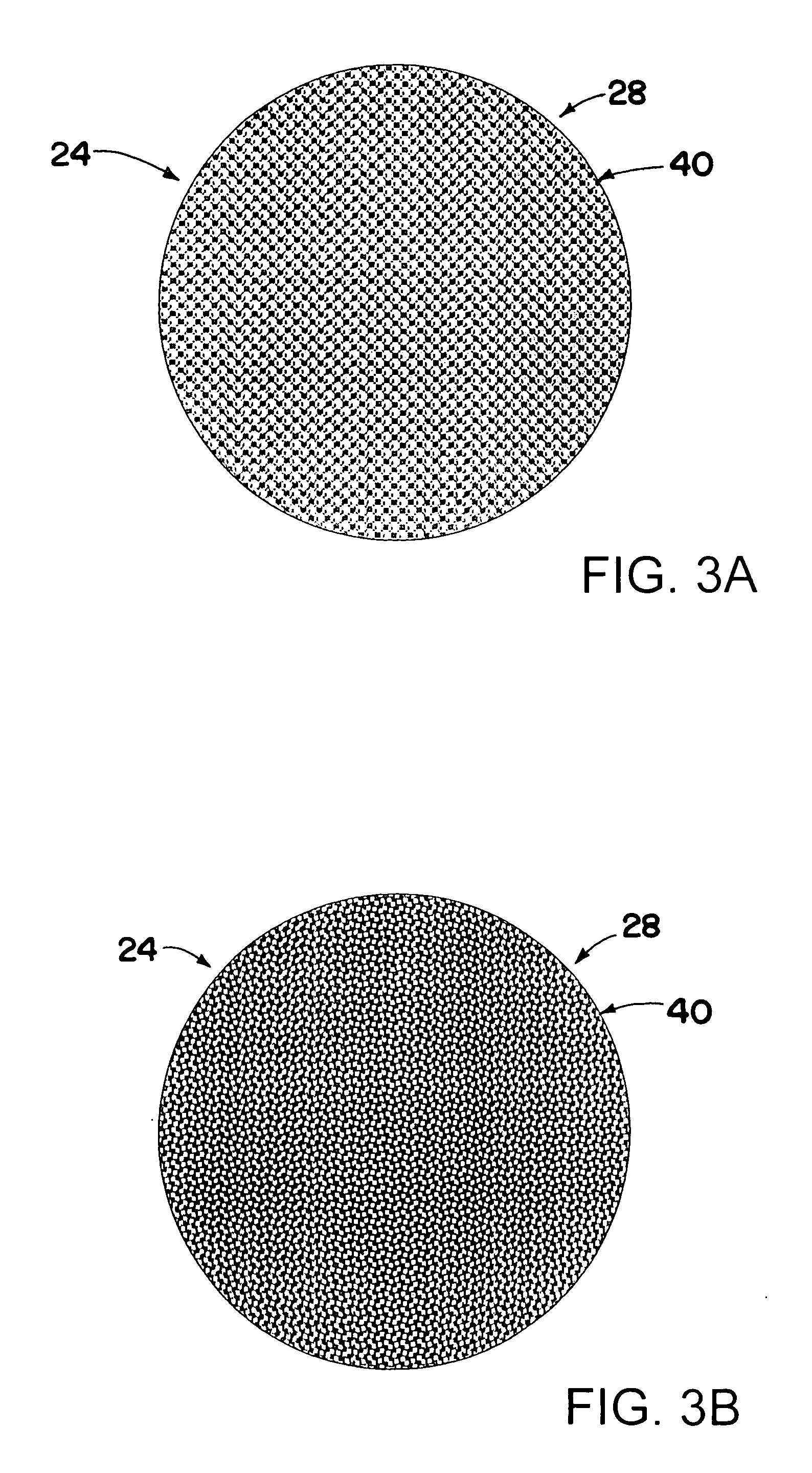
[0023]A radio-frequency-device test range includes a physical space having a source zone for placing an antenna or array of antennas, and a test zone for placing a sensor or other device to be tested. A lens and an apodizer are placed in the physical space between the source zone and the test zone. The lens serves to collimate the energy emanating from the antenna / antenna-array toward the test zone. The lens may be an aspheric lens. The lens may have a surface treatment, such as an anti-reflective coating or a surface pattern, on one or both surfaces. The apodizer functions to keep energy from diffracting off the edge of the lens and getting into the field of view (the test zone). The apodizer may be a resistance (R-Card) fence. The sensor or other device to be tested may be placed on a moveable mount to allow it to be moved, to simulate relative movement of the device and a radio frequency source, such as an antenna. The test zone for the system may have at least a 30 degree field ...


PUM


Abstract

A radio-frequency-device test range (the Refractive Compact Range) includes a physical space having a source zone for placing an antenna or array of antennas, and a test zone for placing a sensor or other device to be tested. A lens and an apodizer are placed in the physical space between the source zone and the test zone. The lens serves to collimate radiated energy emanating from the antenna toward the test zone. The lens may have a surface treatment, such as an anti-reflective coating or a surface pattern, on one or both surfaces. The apodizer functions to keep energy from diffracting off the edge of the lens and getting into the field of view (the test zone). The sensor or other device to be tested may be placed on a moveable mount to allow it to be moved, to simulate relative movement of the device and a radio frequency source, such as radiated by an antenna.

Description

BACKGROUND OF THE INVENTION[0001]1. Technical Field of the Invention[0002]This invention relates generally to systems and methods for testing devices utilizing radio frequency signals.[0003]2. Description of the Related Art[0004]Performing testing on devices utilizing radio frequency signals, for example radar sensors or antenna systems, may involve outdoor testing, in controlled conditions and / or in large buildings, under conditions simulating actual use of the antenna. However, testing outdoors or in a large building under controlled conditions is often impractical and / or expensive, and thus smaller indoor test ranges are often desired and used for testing.[0005]The simplest type of prior art indoor testing facility involves surrounding an interior space with radar-absorbing material, and relying on direct illumination of a sensor by an antenna or antenna array in performing testing. The sensor may be rotated and / or moved in order to examine the effect of orientation and movement ...

Claims


Application Information

Patent Timeline
IPC IPC(8): H01Q15/02
CPCG01R29/105H01Q15/02G01S7/4004
Inventor MARSHALL, DEAN R.KNAPP, DAVID J.
Owner RAYTHEON CO
Why Eureka
Try Eureka