Variable capacitor array

a capacitor array and variable capacitor technology, applied in the direction of instruments, electric digital data processing, input/output processes of data processing, etc., can solve the problems of amplifying non-zero steady state signal, parasitic capacitance level between the screen and some lines, unbalance steady state noise level of lines, etc., to achieve the effect of reducing the output signal of differential amplifiers

Inactive Publication Date: 2007-11-22
N TRIG
View PDF6 Cites 144 Cited by
  • Summary
  • Abstract
  • Description
  • Claims
  • Application Information

AI Technical Summary

Benefits of technology

[0068] An aspect of some embodiments of the invention provides a digitizer comprising a digitizer sensor comprising at least one pair of conductive lines coupled to at least one differential ampl...

Problems solved by technology

However, in practice slight differences in distance between the digitizer and screen, material structure in specific areas of the digitizer screen, environmental conditions and parasitic capacitance on associated PCB, may affect the parasitic capacitance level between the screen and some of the lines.
The unbalanced capacitance creates an unbalance steady state noise level of the lines.
The result is a diff...

Method used


Image

  • Variable capacitor array
  • Variable capacitor array
  • Variable capacitor array

Examples


Embodiment Construction

[0078] In the following description, exemplary, non-limiting embodiments of the invention incorporating various aspects of the present invention are described. For purposes of explanation, specific configurations and details are set forth in order to provide a thorough understanding of the embodiments. However, it will also be apparent to one skilled in the art that the present invention may be practiced without the specific details presented herein. Furthermore, well-known features may be omitted or simplified in order not to obscure the present invention. Features shown in one embodiment may be combined with features shown in other embodiments. Such features are not repeated for clarity of presentation. Furthermore, some unessential features are described in some embodiments.

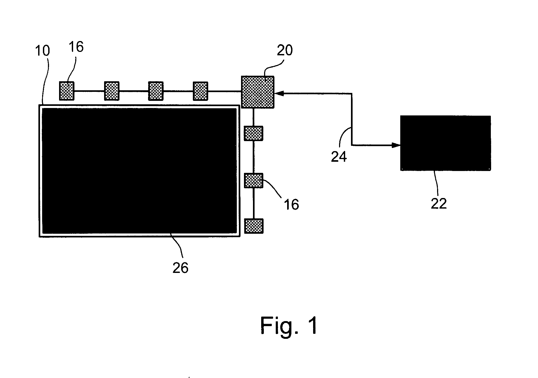
[0079] Reference is now made to FIG. 1 showing an exemplary simplified block diagram of a digitizer system in accordance with some embodiments of the present invention. The digitizer system displayed in FIG. ...


PUM


Abstract

A digitizer includes a digitizer sensor comprising at least one pair of conductive lines coupled to at least one differential amplifier through which a difference signal is detected, and at least one capacitor operative to balance differences in parasitic capacitance between the conductive lines of the at least one pair of conductive lines.

Description

CROSS REFERENCE TO RELATED APPLICATION [0001] The present application claims the benefit under section 35 U.S.C. §119(e) of U.S. Provisional Application No. 60 / 801,394 filed on May 19, 2006 which is hereby incorporated by reference.FIELD OF THE INVENTION [0002] The present invention relates to digitizing tablet systems and more particularly to unbalanced capacitance in digitizing tablet systems. BACKGROUND OF THE INVENTION [0003] Digitizing tablet systems that allow a user to operate a computing device with a stylus and / or fingertip are known. Typically, a digitizer is integrated with a display screen, e.g. over-laid on the display screen, to correlate user input, e.g. physical touch or stylus interaction on the screen with the virtual information portrayed on it. Position detection of the stylus and / or finger tip provides input to the computing device and is interpreted as user commands. [0004] U.S. Pat. No. 6,690,156 entitled “Physical Object Location Apparatus and Method and a Pl...

Claims


Application Information

Patent Timeline
IPC IPC(8): G06F3/041
CPCG06F3/044G06F3/0446
Inventor PERSKI, HAIMBEN-ELIYAHU, AVI EZEREILON, NIR
Owner N TRIG
Why Eureka
Try Eureka