
Operational amplifier generating desired feedback reference voltage allowing improved output characteristic

a technology of feedback reference voltage and amplifier, which is applied in the direction of different amplifiers, amplifiers with semiconductor devices/discharge tubes, dc-amplifiers with dc-coupled stages, etc., can solve the problems of consideration, and achieve the effect of maximum operable range and suitable output characteristics

Inactive Publication Date: 2006-01-10
RENESAS TECH CORP
View PDF6 Cites 10 Cited by
  • Summary
  • Abstract
  • Description
  • Claims
  • Application Information

AI Technical Summary

Benefits of technology

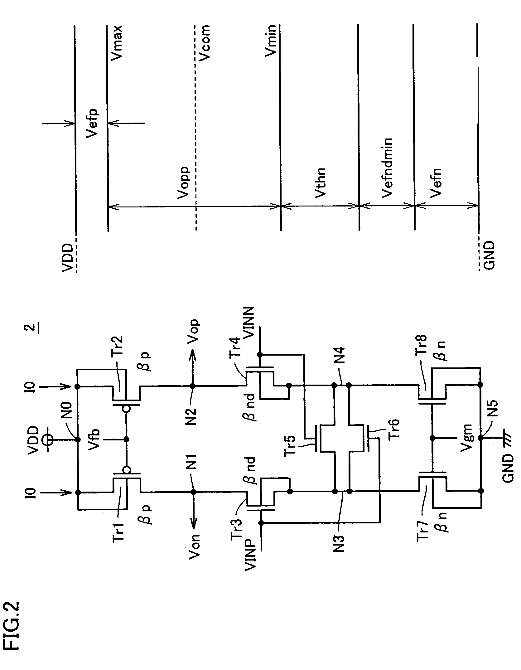
[0011]The present invention, as has been described above, allows a voltage setting circuit to include: a first voltage setting portion setting as based on a current flowing through a pseudo current path portion a voltage level of a first internal node to be a first voltage corresponding to a voltage level allowing at least one of two output signals to be maximized in amplitude, a second voltage setting portion setting as based on the current flowing through the pseudo current path portion a voltage level of a second internal node to be a second voltage corresponding to a voltage level allowing at least one of the two output signals to be minimized in amplitude, and an intermediate voltage setting portion setting an average value of the first and second voltages for a voltage output node. Accordingly, a voltage corresponding to a center of an amplitude of a differential amplification circuit, or an optimal reference voltage can be set. A maximum operable range can be ensured and suitable output characteristic can be obtained.

Problems solved by technology

It is difficult, however, to consider the OTA circuit's process variation or the like to optimally adjust a voltage level.

Method used


Image

  • Operational amplifier generating desired feedback reference voltage allowing improved output characteristic
  • Operational amplifier generating desired feedback reference voltage allowing improved output characteristic
  • Operational amplifier generating desired feedback reference voltage allowing improved output characteristic

Examples


first embodiment

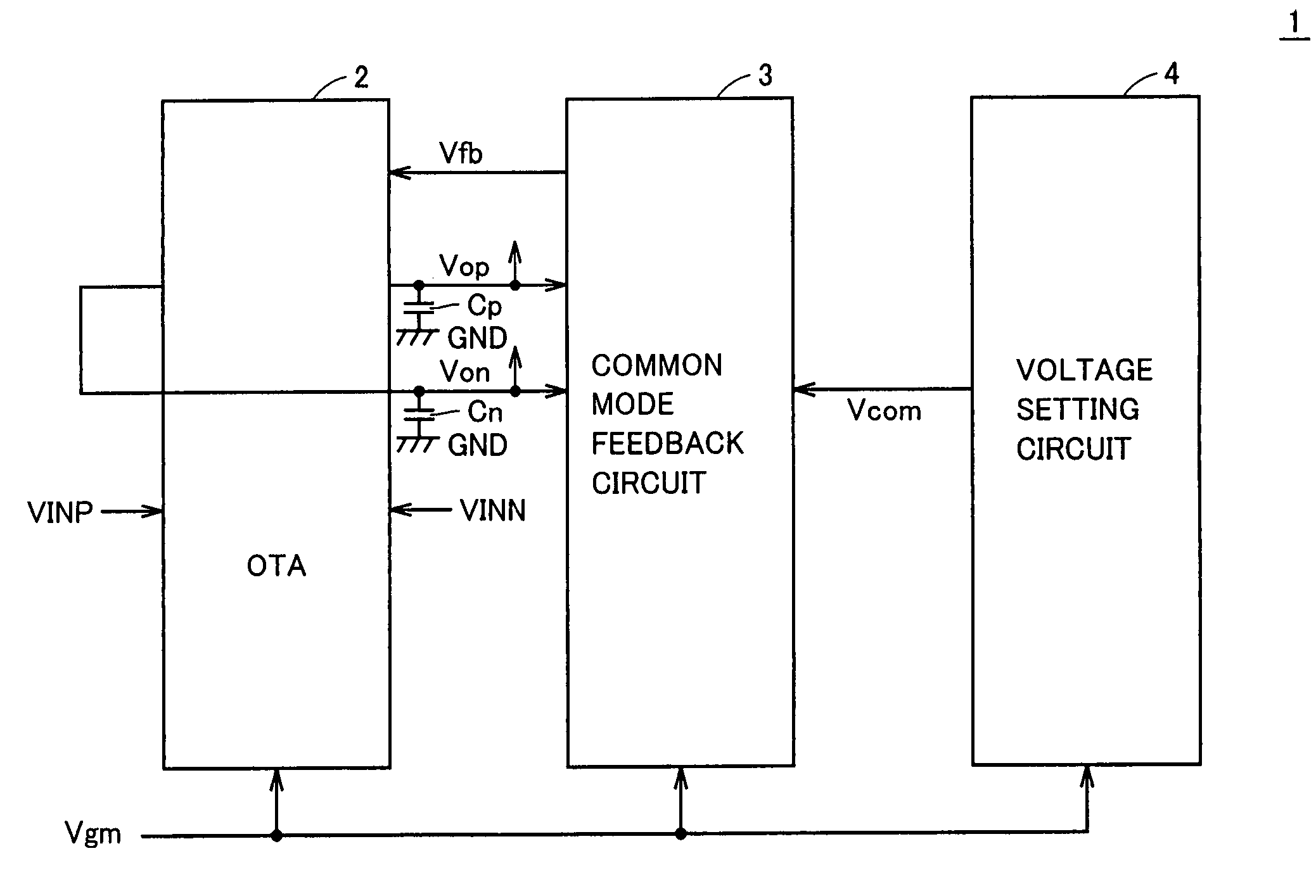
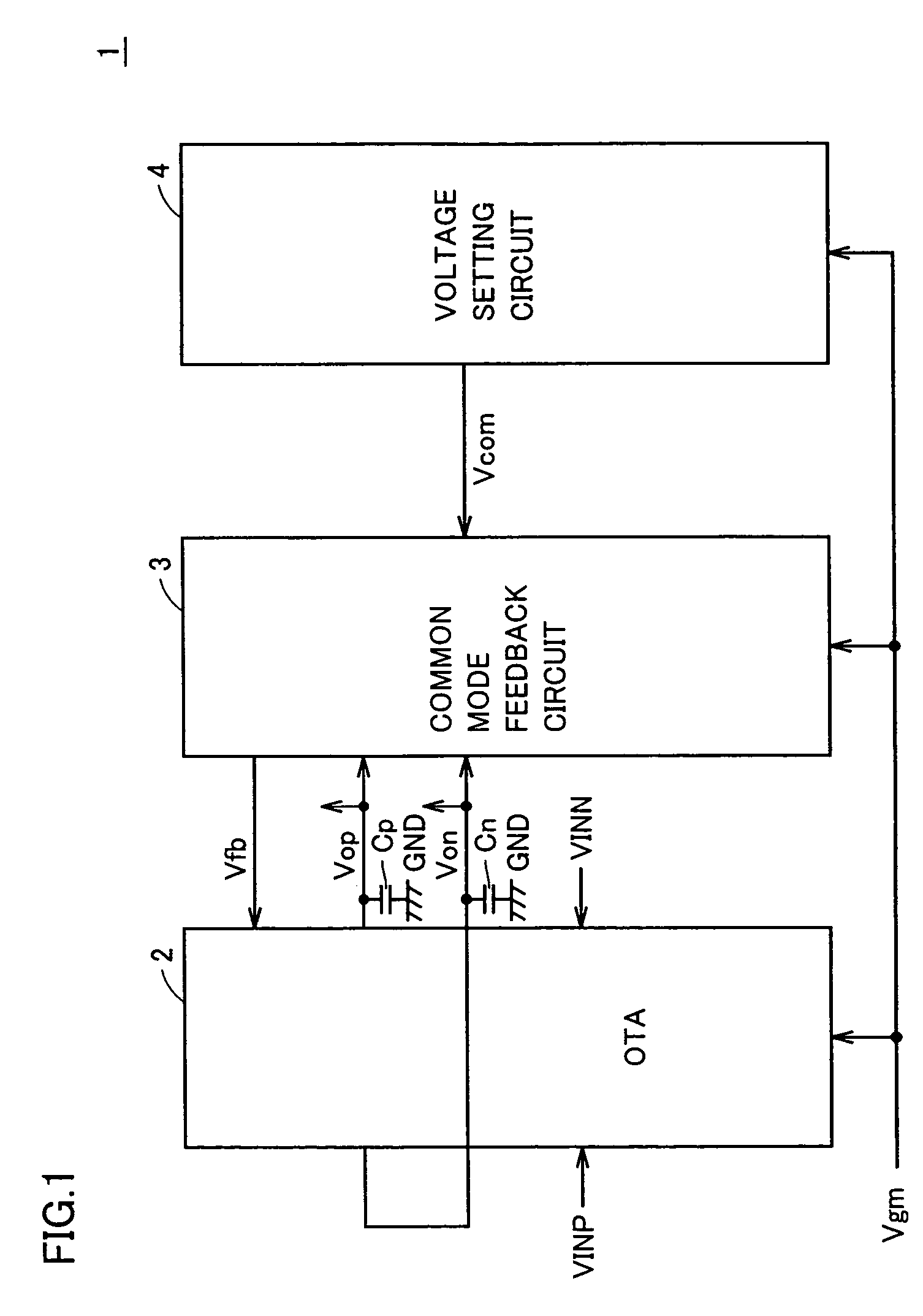
[0024]With reference to FIG. 1, the present invention in a first embodiment provides an operational amplifier 1 including an OTA circuit 2, a common mode feedback circuit 3, a voltage setting circuit 4, and capacitors Cp and Cn.

[0025]OTA circuit 2 receives differential input signals VINP and VINN to amplify their difference in voltage to generate differential output signals Vop and Von.

[0026]Capacitors Cp and Cn are connected between an output line of OTA circuit 2 and a ground voltage GND. More specifically, capacitor Cp is connected between a line outputting differential output signal Vop and ground voltage GND. Capacitor Cn is connected between a line outputting differential output signal Von and ground voltage GND. Differential output signals Vop and Von correspond to voltages of integrals of currents flowing from OTA circuit 2 into capacitors Cp and Cn, respectively.

[0027]Common mode feedback circuit 3 feeds back a feedback control signal Vfb to OTA circuit 2, as based on diffe...


PUM


Abstract

A voltage setting circuit includes a voltage setting region setting a voltage level corresponding to a maximum value in amplitude of a signal output from an OTA circuit, a voltage setting region setting a voltage level corresponding to a minimum value in amplitude of the signal, and an intermediate voltage setting region setting a voltage intermediate between the voltages set by the above two regions. This intermediate voltage is input to a common mode feedback circuit and in accordance with the intermediate voltage the common mode feedback circuit generates a common mode voltage fed back to the OTA circuit.

Description

BACKGROUND OF THE INVENTION[0001]1. Field of the Invention[0002]The present invention relates generally to operational amplifiers and particularly to differential transconductance amplifiers that can monolithically integrated by CMOS technology.[0003]2. Description of the Background Art[0004]In recent years, LSIs and the like used to process an RF band signal in mobile communications employ a so-called Gm-C filter serving as a bandpass filter. This Gm-C filter is provided as a circuit having as its base an operational transconductance amplifier (hereinafter also referred to as an OTA circuit) performing voltage-current conversion. While this OTA circuit belongs in a broad sense to an operational amplifier, it also has a high output impedance for a closed loop, and is used for a variety of circuits for general purpose. Generally, this OTA circuit is arranged together with a so-called common mode feedback circuit and in response to the OTA circuit's differential output signal the comm...

Claims


Application Information

Patent Timeline
Patent Type & Authority Patents(United States)
IPC IPC(8): H03F3/45H03G3/12
CPCH03F3/45183H03F3/45937H03F3/45641
Inventor MIWA, TOSHITSUGUMIKI, TAKAHIRO
Owner RENESAS TECH CORP
Learn More