Sensor-equipped bearing for wheel

a technology for supporting bearings and wheels, which is applied in the direction of apparatus for force/torque/work measurement, instruments, transportation and packaging, etc., can solve the problems of insufficient detection sensitivity, small strain, and hysteresis in output signals, so as to facilitate processing of sensor units and installation of sensors. , the effect of easy installation

Inactive Publication Date: 2010-05-27
NTN CORP
View PDF34 Cites 13 Cited by
  • Summary
  • Abstract
  • Description
  • Claims
  • Application Information

AI Technical Summary

Benefits of technology

[0025]In the present invention, the entire surface of a predetermined surface portion including a sensor installing surface in the strain generating member may be a flat plane. In the case of this construction, processing of the sensor unit and installation of the sensor can be facilitated.
[0026]In the present invention, while the entire surface of a predetermined surface portion that contains a sensor installing surface in the strain generating member is rendered to be a flat plane, the strain generating member may be fixed to the outer diametric surface of the stationary member through spacers. At a portion of an inner side surface of the strain generating member other than the remaining portion thereof where the spacer intervene, a gap tends to be formed between it and the outer diametric surface of the stationary member and the sensor can also be easily installed in the vicinity of the cutout portion without being interfered with the outer diametric surface of the stationary member.
[0027]In the present invention, the sensor may be provided in the proximity of the cutout portion in the strain generating member and, while the entire surface of a predetermined surface portion including a sensor installing surface in the strain generating member is rendered to be a flat plane, grooves may be provided between fixing positions of the two contact fixing segments of the sensor unit in the outer diametric surface of the stationary member. Where the grooves are provided in the outer diametric surface of the stationary member as hereinabove described, and where the flat plane of the strain generating member is an inner side surface opposed to the outer diametric surface of the stationary member, the gap tends to be formed between the outer diametric surface of the stationary member and the inner side surface, which is represented by the flat plane of the strain generating member, and, therefore, the sensor can also be easily installed at a location proximate to the cutout portion without being interfered with the outer diametric surface of the stationary member.
[0028]In the present invention, a vehicle body fitting flange, which is adapted to be coupled to a knuckle, may be provided on an outer periphery of the stationary member, bolt holes may be provided in this vehicle body fitting flange at a plurality of locations circumferentially thereof, circumferential portions of the flange, where the bolt holes are provided, may be rendered to be projecting segments protruding radially beyond the remaining portion thereof, and the sensor unit may be arranged at a middle portion between the neighboring projecting segments. In the case of this construction, the sensor can be installed at a location remote from the projecting segments, which form a cause of hysteresis, and, therefore, the hysteresis of the output signal of the sensor can be further reduced, allowing the load to be further accurately detected.
[0029]In the present invention, the stationary member may have a portion thereof provided with a thick walled portion that is locally thick in wall. When the load acts between the tire of the vehicle wheel and the road surface, the load is also applied to the stationary member (for example, the outer member) of the wheel support bearing assembly accompanied by deformation. Accordingly, if an attempt is made to calculate the load from the deformation of the vehicle body fitting flange while the sensor unit is fixed to, for example, the vehicle body fitting flange, hysteresis occurs in the output signal. Particularly where an attempt is made to detect through the strain generating member of the sensor unit, the strain of the stationary that is amplified, a considerable influence is brought about by the hysteresis on the output signal. However, the provision of the thick walled portion in that portion of the stationary member make it possible for the thick walled portion to have an increased rigidity with the amount of deformation reduced and, therefore, to provide a location where the influence brought about by the hysteresis is small. Formation of this thick walled portion makes it possible to provide a location, where the amount of deformation is small and the influence brought about by the hysteresis is small, at a location different from the vehicle body fitting flange. In view of this, when the sensor unit is to be fixed to the stationary member, one of the contact fixing segments of the strain generating member is fixed to a location proximate to, for example, the thick walled portion and the other of the contact fixing segments is fixed to a location proximate to, for example, the rolling surface in the stationary member, where the amount of deformation is relatively large. By so doing, the strain occurring in the stationary member is transmitted to the strain generating member in the form as amplified and this amplified strain can be detected by the sensor. For this reason, a working force developed between the tire of the vehicle wheel and the road surface can be detected with high sensitivity and, also, the hysteresis occurring in the output signal of the senor comes to be minimized. As a result, without being affected by the hysteresis, the load imposed on the vehicle wheel can be detected accurately.
[0030]In the present invention, the stationary member may be the outer member and the thick walled portion referred to above may be provided in a portion of the outer periphery of the stationary member in an outboard end portion thereof. Where the stationary member is the outer member, as compared with the case where the stationary member is assumed by the inner member, not only can the strain be detected with high sensitivity, but also an effect of reducing the hysteresis, which results from the formation of the thick walled portion, can be obtained easily. Also, the provision of the thick walled portion in that portion of the outer periphery adjacent the outboard end permits it to be provided at a location remote from the vehicle body fitting flange that is susceptible to influence brought about by a slippage if it exceeds the stationary frictional force. For this reason, the hysteresis of the output signal of the sensor is further reduced, allowing the load to be detected with further accuracy. Also, if the stationary member is the outer member, a relatively large space is available in the outer periphery adjacent the outboard side and, therefore, the thick walled portion can be easily provided there.

Problems solved by technology

A problem has, however, been found that since the deformation of the stationary ring is accompanied by slippage between a flange surface and a knuckle surface in the event that a force of a magnitude exceeding a stationary frictional force acts, a hysteresis tends to occur in an output signal when load is applied repeatedly.
Also, even in the technique disclosed in the Patent Document 2 listed above, a portion of the strain amplifying mechanism comprised of the L-shaped member, which is fixed to the flange surface, tends to be affected by a slippage occurring between the flange surface and the knuckle surface and, therefore, a problem similar to that discussed previously occurs.
Additionally, in the case of detecting a vertical load Fz acting on the wheel support bearing assembly, amount of deformation of the stationary member is small relative to the load Fz, resulting in small amount of the strain.
Accordingly, a sufficient detection sensitivity is not obtained with the technique discussed above and therefore the load Fz can not be detected accurately.

Method used


Image

  • Sensor-equipped bearing for wheel
  • Sensor-equipped bearing for wheel
  • Sensor-equipped bearing for wheel

Examples


first embodiment

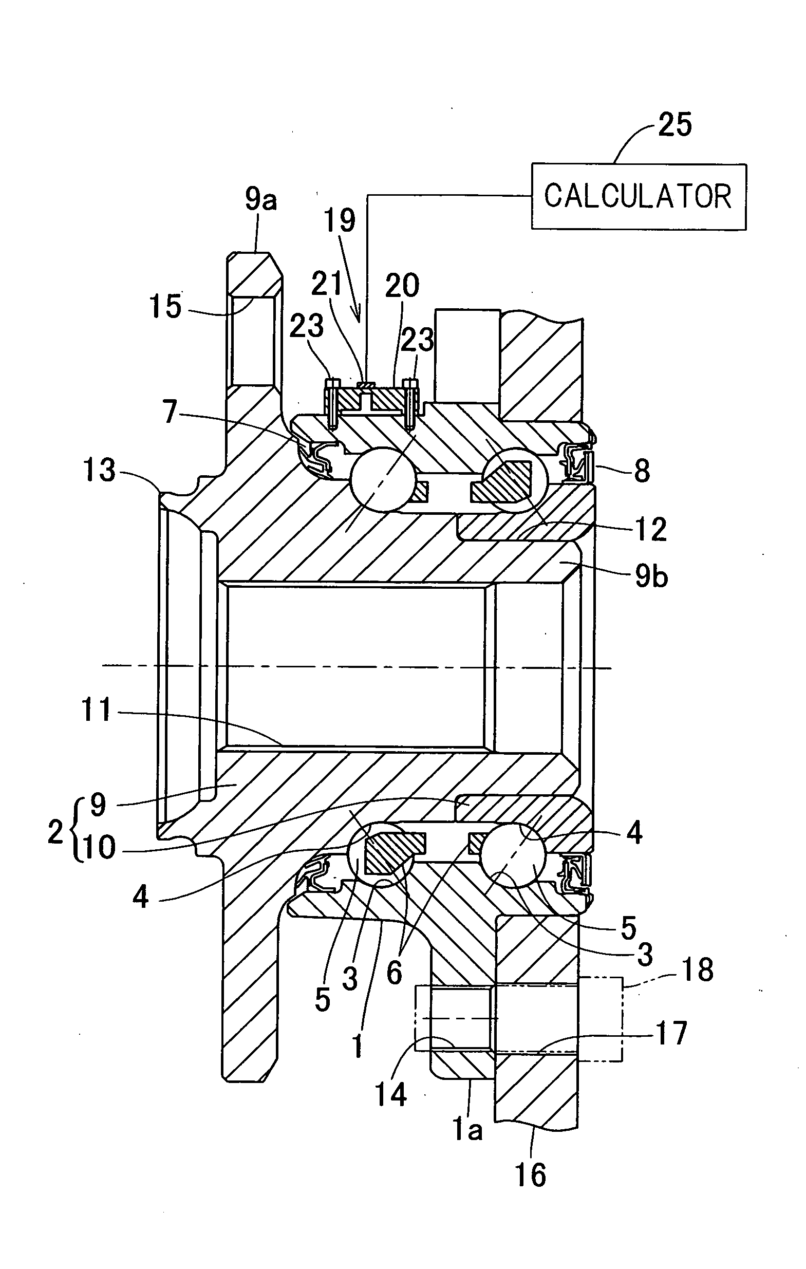
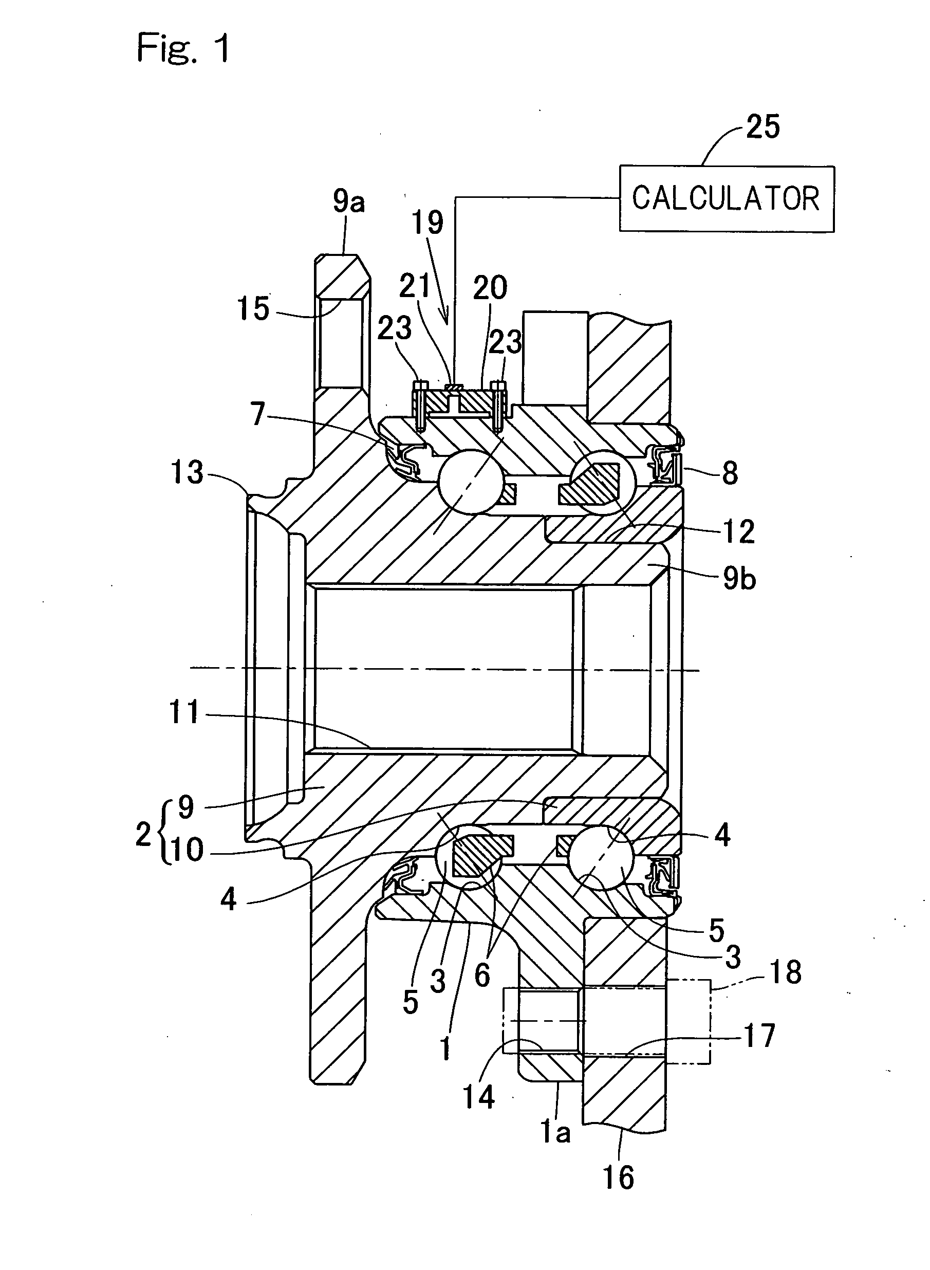
[0064]the present invention will now be described in detail with particular reference to FIGS. 1 to 3. This embodiment is directed to a inner ring rotating type wheel support bearing assembly of a third generation model, which is used to rotatably support a vehicle drive wheel. It is to be noted that in the description that follows, one side of a vehicle body structure laterally away from the longitudinal center thereof in a condition, in which the bearing assembly is mounted on the vehicle body structure, is referred to as “outboard side” while the opposite side of the vehicle body structure laterally close towards the longitudinal center thereof in the same condition is referred to as “inboard side”.

[0065]A bearing unit employed in this sensor-equipped wheel support bearing assembly includes, as shown in a sectional view in FIG. 1, an outer member 1 having an inner periphery formed with a plurality of rolling surfaces 3, an inner member 2 having rolling surfaces 4 defined therein ...

second embodiment

[0090]Other structural features are similar to those shown in and described with reference to FIGS. 5 to 7 in connection with the previously described It is to be noted that the counterbore 22a may only be provided in the bolt insertion hole 22 with the chamfered corner portion 26 dispensed with. The formation of the counterbore 22a in the bolt insertion hole 22 allows the head 23a of the bolt 23 to be buried within the surface portion 20aa of the contact fixing segment 20a and, therefore, any possible interference of the bolt head 23a with the hub bolts 13 can be avoided advantageously. Also, mere formation of the counterbore 22a in the bolt insertion hole 22 is so sufficient that the shape effective to avoid the interference with the hub bolts can be obtained with a simple processing.

[0091]Hereinafter, a fifth embodiment of the present invention will be described in detail with particular reference to FIGS. 10 to 13A and 13B. In those figures, component parts similar to those sho...

fifth embodiment

[0092]In this fifth embodiment of the present invention, the cutout portion 20c is formed in the strain generating member 20 of the sensor unit 19 at a location on the outboard side and remote from the middle portion between the two contact fixing segments 20a and 20b. As shown in FIGS. 12A and 12B showing one example of the structure of the sensor unit 19 in a front elevational view and a bottom plan view (a representation as viewed from the inner surface side confronting the outer diametric surface of the outer member 1), respectively, the illustrated instance utilizes the cutout portion 20c of such a shape that a portion of the outer surface of the strain generating member 20 is cut out inwardly of the strain generating member 20 towards an inner surface thereof. This cutout portion 20c has a widthwise dimension that is rendered to be 2 mm or smaller. The sensor 21 is pasted to an area of the strain generating member 20, where the strain occurs considerably relative to a load act...


PUM


Abstract

A sensor-equipped wheel support bearing assembly, in which a load imposed on the wheel can be accurately detected without influences from hysteresis is provided. This wheel support bearing assembly includes an outer member having a plurality of rolling surfaces, an inner member having rolling surfaces opposed respectively to the rolling surfaces of the outer member, and rolling elements between the rolling surfaces. A sensor unit is provided in a stationary member of one of the outer and inner members, which unit includes a strain generating member having two contact fixing segments to be fixed to the stationary member and a sensor fitted to the strain generating member for detecting a strain induced in this strain generating member. The two contact fixing segments are arranged at respective positions held at the same phase in a direction circumferentially of the stationary member.

Description

CROSS REFERENCE TO THE RELATED APPLICATION[0001]This application is based on and claims priority to Japanese patent applications No. 2007-199216, No. 2007-199217, No. 2007-199219 and No. 2007-199220, all filed Jul. 31, 2007, the entire disclosures of which are herein incorporated by reference as a part of this application.BACKGROUND OF THE INVENTION[0002]1. Field of the Invention[0003]The present invention relates to a sensor-equipped wheel support bearing assembly having a load sensor built therein for detecting a load imposed on a bearing unit of a vehicle wheel.[0004]2. Description of the Related Art[0005]As a technique for detecting a load imposed on each of vehicle wheels employed in an automotive vehicle, a sensor-equipped wheel support bearing assembly has been suggested, with which the load is detected by detecting a strain occurring in an outer diametric surface of an outer ring flange of a wheel support bearing assembly. (See, for example, the Patent Document 1 listed belo...

Claims


Application Information

Patent Timeline
Patent Type & Authority Applications(United States)
IPC IPC(8): F16C32/00
CPCB60B27/0005B60B27/0068B60B27/0094G01L5/0019F16C19/522F16C33/58F16C19/186F16C33/586F16C41/007F16C2233/00F16C2326/02
Inventor ISOBE, HIROSHITAKAHASHI, TORUOZAKI, TAKAYOSHI
Owner NTN CORP
Why Eureka
Try Eureka