Perpendicular magnetic recording head and magnetic disk apparatus
a technology of magnetic recording head and magnetic disk, which is applied in the direction of data recording, instruments, heads with metal sheet cores, etc., can solve the problems of difficult to improve the density of the track, disadvantageously erase a part of the signal already recorded in the adjacent track, and the longitudinal direction of the main pole may skew significantly relative to the track direction
- Summary
- Abstract
- Description
- Claims
- Application Information
AI Technical Summary
Problems solved by technology
Method used
Image
Examples
first embodiment
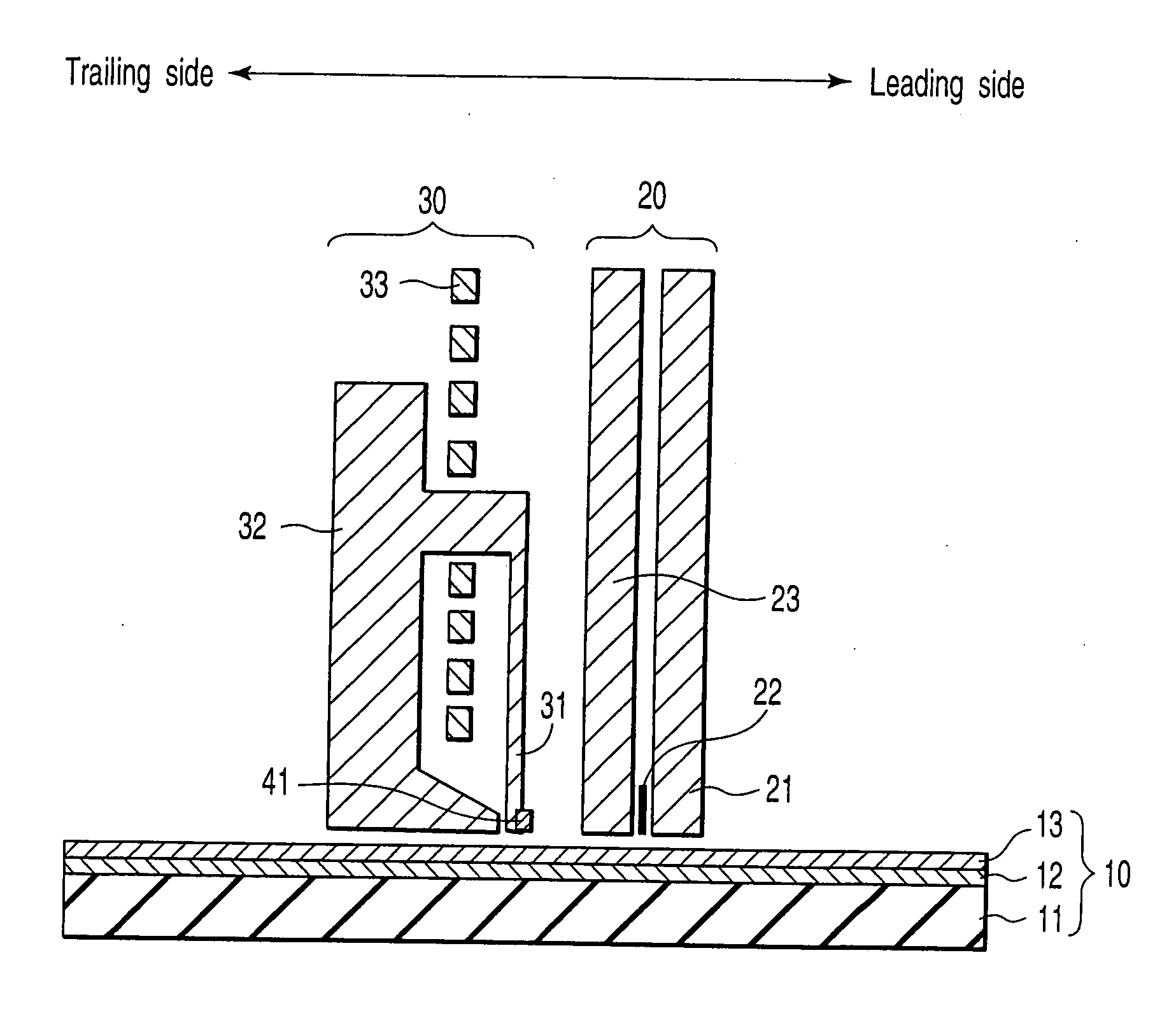
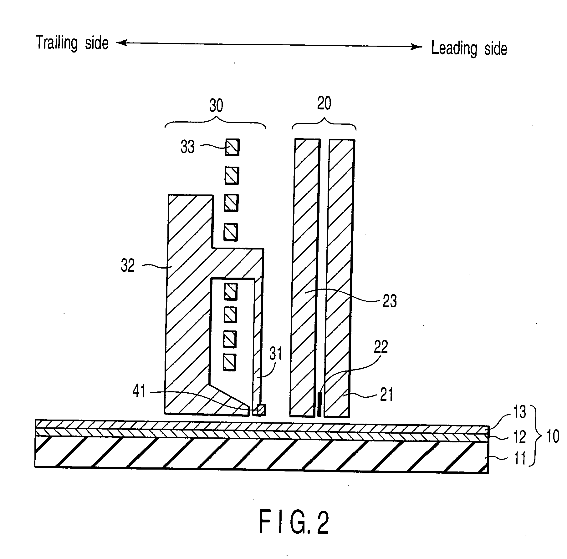
[0032]FIG. 2 is a cross-sectional view showing a perpendicular magnetic disk apparatus including a magnetic head according to the present invention and a perpendicular recording medium. FIG. 3 is a perspective view showing the write head in FIG. 2. FIG. 4 is a plan view of the write head in FIG. 2 as viewed from the air bearing surface (ABS).
[0033] A magnetic disk 10 is a perpendicular double-layer medium including a substrate 11, and a soft underlayer 12 and a perpendicular recording layer 13 with magnetic anisotropy in the perpendicular direction to the disk plane, which are provided on the substrate 11.
[0034] The magnetic head is of a separate type having a read head 20 and a write head 30 separated to each other. The read head 20 is composed of a magnetoresistive film 22 and shield films 21 and 23 located on the leading side and the trailing side of the magnetoresistive film 22.
[0035] The write head has the main pole 31 comprising a high-permeability material that generates re...
second embodiment
[0041]FIG. 5 is a plan view of a write head according to the preset invention as viewed from ABS. In this figure, the width of the leading edge of the main pole 31 is almost equal to the width of the trailing edge thereof. Side shields 42 are located in the vicinity of the leading side of the main pole 31 so as to be divided into two parts located on the both sides of the main pole 31. The side edges of the two side shields 42 are formed along the side edges of the main pole 31, respectively.
third embodiment
[0042]FIG. 6 is a plan view of a write head according to the preset invention as viewed from ABS. In this figure, the width of the leading edge of the main pole 31 is almost equal to the width of the trailing edge thereof. Side shields 43 are located in the vicinity of the leading side of the main pole 31 so as to be divided into two parts located on the both sides of the main pole 31. The distance between the side edges of the two side shields 43 and the main pole 31 is shorter on the leading side and longer on the trailing side.
PUM
 Abstract
Description
Claims
Application Information
 - R&D
- Intellectual Property
- Life Sciences
- Materials
- Tech Scout
- Unparalleled Data Quality
- Higher Quality Content
- 60% Fewer Hallucinations
Browse by: Latest US Patents, China's latest patents, Technical Efficacy Thesaurus, Application Domain, Technology Topic, Popular Technical Reports.
© 2025 PatSnap. All rights reserved.Legal|Privacy policy|Modern Slavery Act Transparency Statement|Sitemap|About US| Contact US: help@patsnap.com


