
Backlight assembly, liquid crystal display apparatus having the same and method thereof

Active Publication Date: 2007-11-22
SAMSUNG DISPLAY CO LTD
View PDF8 Cites 29 Cited by
  • Summary
  • Abstract
  • Description
  • Claims
  • Application Information

AI Technical Summary

Benefits of technology

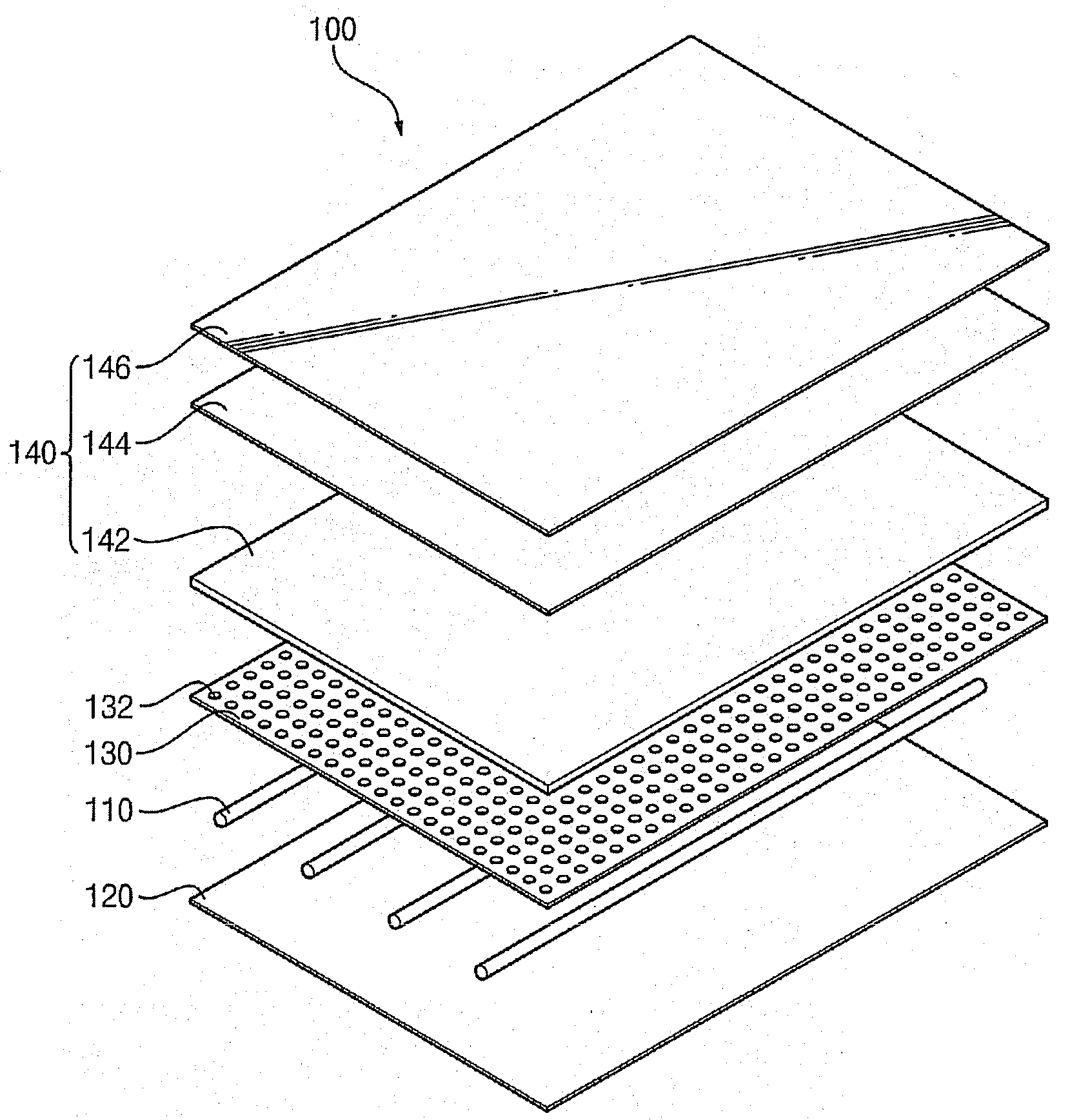
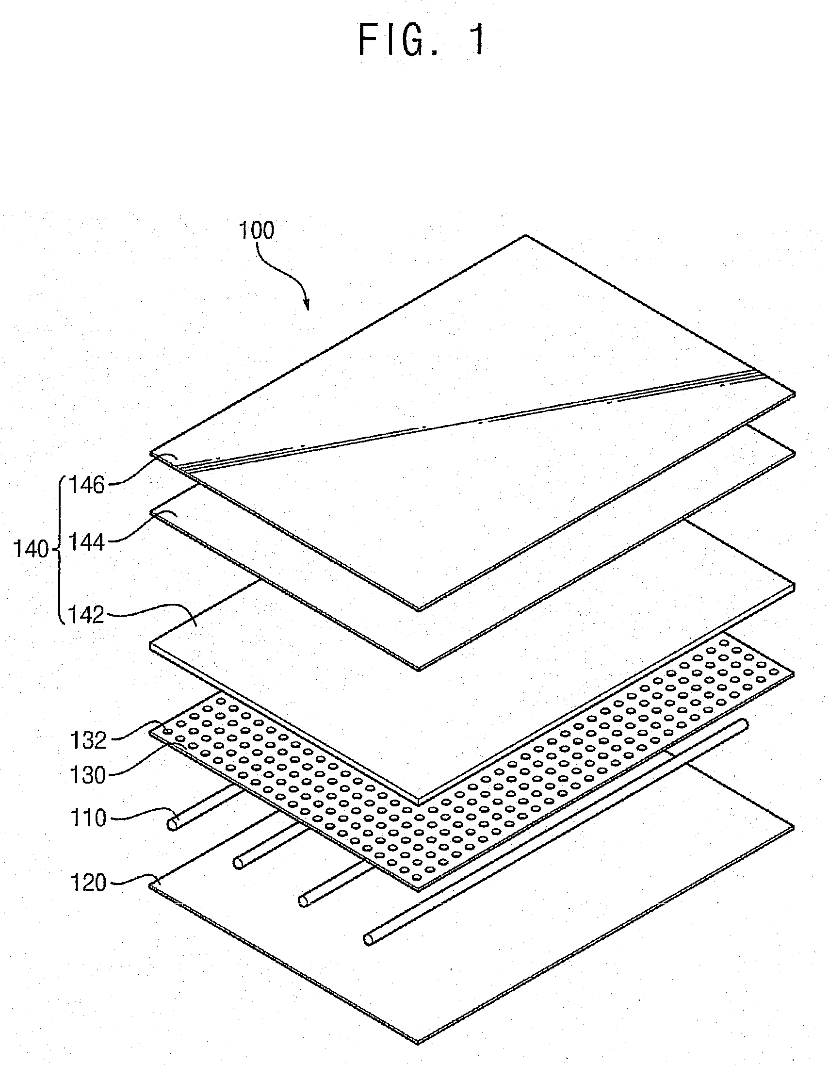
[0008]An exemplary embodiment provides a backlight assembly capable of increasing an optical efficiency despite having a similar thickness to an edge-illumination type, and reducing a manufacturing cost through excluding a light guide plate.
[0016]In an exemplary embodiment, a method of forming a backlight display provides forming a first reflecting plate including a transmission region transmitting light and a reflective region reflecting light generated by a plurality of lamps, disposing a second reflecting plate under the plurality of lamps generating the light; and disposing the first reflecting plate over the plurality of lamps generating the light. The forming a first reflecting plate includes forming a plurality of penetration holes in the transmission region. A formation density of the penetration holes is increased in an intermediate region between adjacent lamps from a lamp region.
[0017]According to the above mentioned backlight assembly and display apparatus having the backlight assembly, an optical efficiency may improve. A light guide plate may be excluded, so that a thickness of a backlight assembly may be reduced and a manufacturing cost may be retrenched.

Problems solved by technology

The edge-illumination type backlight assembly has an advantage of a thinner thickness, but an optical efficiency of the edge-illumination type backlight assembly is relatively low and a cost of the device increases due to the light guide plate.
The direct-illumination type backlight assembly has an advantage of a high brightness, but a thickness and a cost of the direct-illumination type backlight assembly increase due to the numerous lamps.

Method used


Image

  • Backlight assembly, liquid crystal display apparatus having the same and method thereof
  • Backlight assembly, liquid crystal display apparatus having the same and method thereof
  • Backlight assembly, liquid crystal display apparatus having the same and method thereof

Examples


Embodiment Construction

[0028]The present invention now will be described more fully hereinafter with reference to the accompanying drawings, in which embodiments of the invention are shown. This invention may, however, be embodied in many different forms and should not be construed as limited to the embodiments set forth herein; rather, these embodiments are provided so that this disclosure will be thorough and complete, and will fully convey the scope of the invention to those skilled in the art. It will be understood that when an element is referred to as being “on” or “onto” another element, it may be directly on the other element or intervening elements may also be present. In contrast, when an element is referred to as being “directly on” another element, there are no intervening elements present. Like reference numerals refer to similar or identical elements throughout. In the drawings, the size and relative sizes of layers and regions may be exaggerated for clarity.

[0029]It will be understood that,...


PUM


Abstract

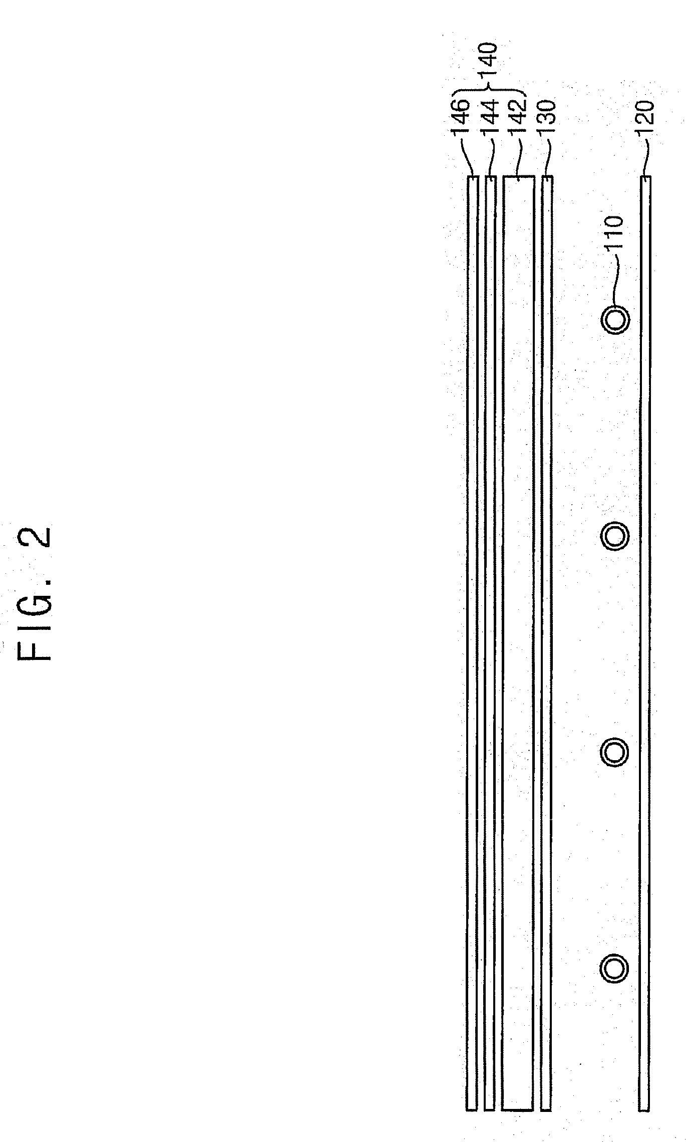
A backlight assembly includes a plurality of lamps, a first reflecting plate and an optical member. The lamps are disposed substantially parallel with each other and generate light. The bottom reflecting plate is disposed under the lamps to reflect the light. The first reflecting plate is disposed over the lamps to transmit and reflect the light and has a plurality of penetration holes for transmitting the light. The optical member is disposed over the first reflecting plate. The formation density of the penetration holes increases as a position of the penetration holes approaches an intermediate region between adjacent lamps from a region corresponding to a position of the lamps.

Description

[0001]This application claims priority to Korean Patent Application No. 2006-45390 filed on May 20, 2006, and all the benefits accruing therefrom under 35 U.S.C. §119, the contents of which are herein incorporated by reference in its entirety.BACKGROUND OF THE INVENTION[0002]1. Field of the Invention[0003]The present invention relates to a backlight assembly and a display apparatus having the backlight assembly. More particularly, the present invention relates to a backlight assembly capable of reducing a manufacturing cost and decreasing a thickness of the backlight assembly, and a display apparatus having the backlight assembly.[0004]2. Description of the Related Art[0005]A liquid crystal display (“LCD”) apparatus needs a backlight assembly to provide an LCD panel with light because the LCD panel displaying images is a non-luminous device, which does not emit light by itself.[0006]The backlight assembly may be classified as either an edge-illumination type or a direct-illumination...

Claims


Application Information

Patent Timeline
IPC IPC(8): F21V7/04
CPCG02F1/133604G02F1/133606G02F1/133605G02F1/1335
Inventor JUNG, DAE-YOONLEE, KWANG-HOON
Owner SAMSUNG DISPLAY CO LTD
Learn More